Power supply apparatus and image forming apparatus

a technology of power supply apparatus and image forming apparatus, which is applied in the field of power supply, can solve the problems of reducing the size and weight of the power supply apparatus that cannot be easily realized, conductive rubber will eventually deteriorate, so as to reduce the influence of surge curren

Inactive Publication Date: 2014-01-28
CANON KK
View PDF7 Cites 6 Cited by
  • Summary
  • Abstract
  • Description
  • Claims
  • Application Information

AI Technical Summary

Benefits of technology

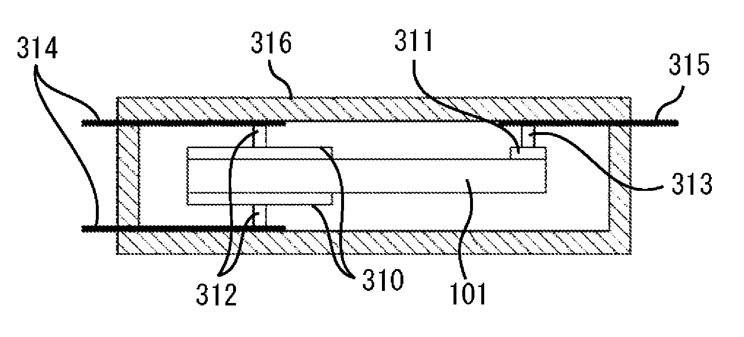
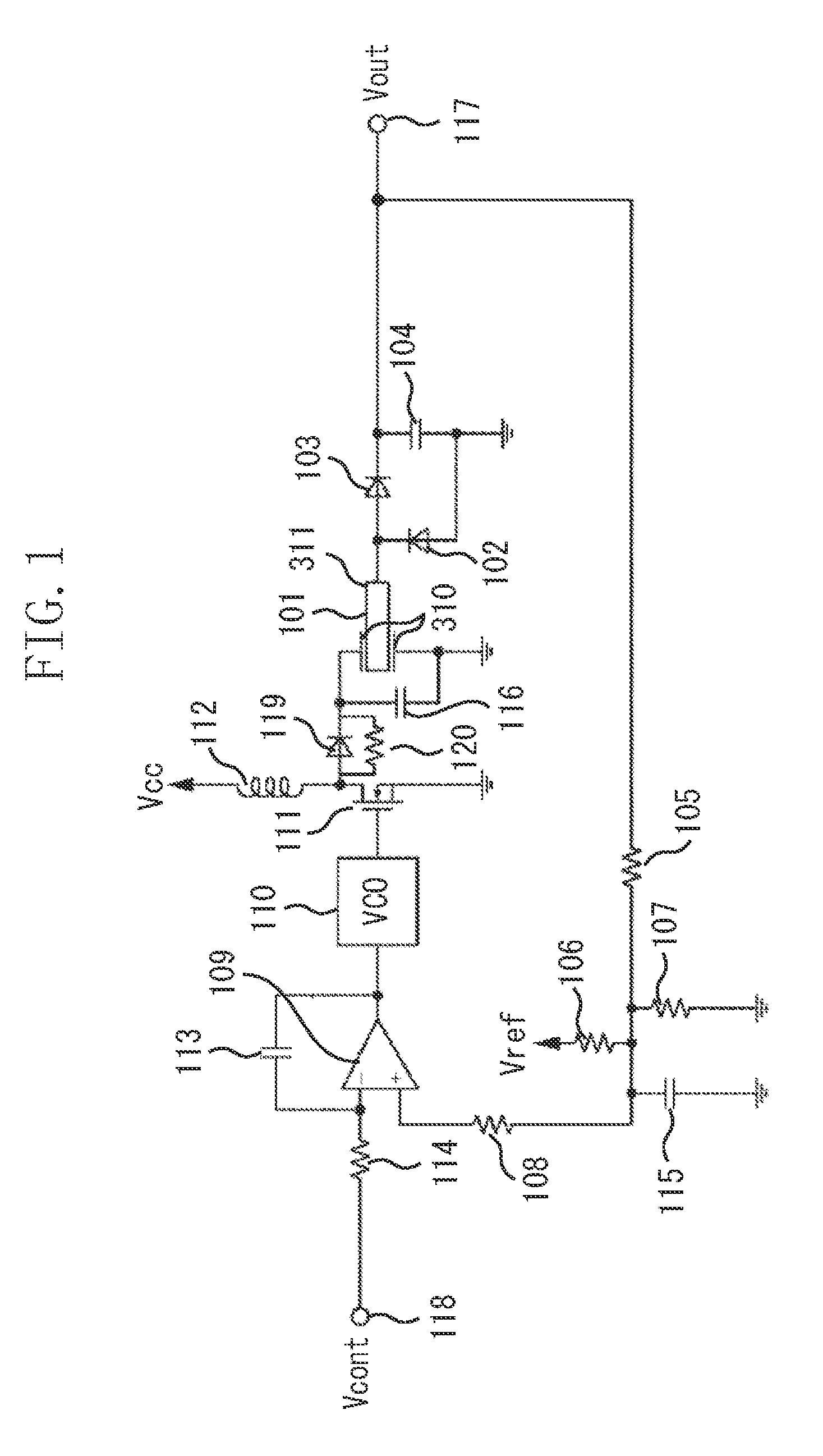
[0013]The present invention is directed to a power supply apparatus that enables to connect a substrate and a piezoelectric transformer using a conductive rubber, to protect the conductive rubber from a surge current, and to reduce an influence of the surge current on a drive voltage of the piezoelectric transformer, and to an image forming apparatus that includes the power supply apparatus.

Problems solved by technology

For this purpose, insulating the electromagnetic transformer by a mold or the like is absolutely necessary, and accordingly reduction in size and reduction in weight of the power supply apparatus could not be easily realized.
Therefore, the conductive rubber will be eventually deteriorated by the surge current each time the power supply outputs a high-voltage.
Consequently, for example, like the above-described image forming apparatus, when the piezoelectric transformer is used for an apparatus that needs to output a high-voltage frequently and for long period of time for an image forming, the conductive rubber will be eventually deteriorated.
Consequently, it becomes difficult to endure a long-term use.
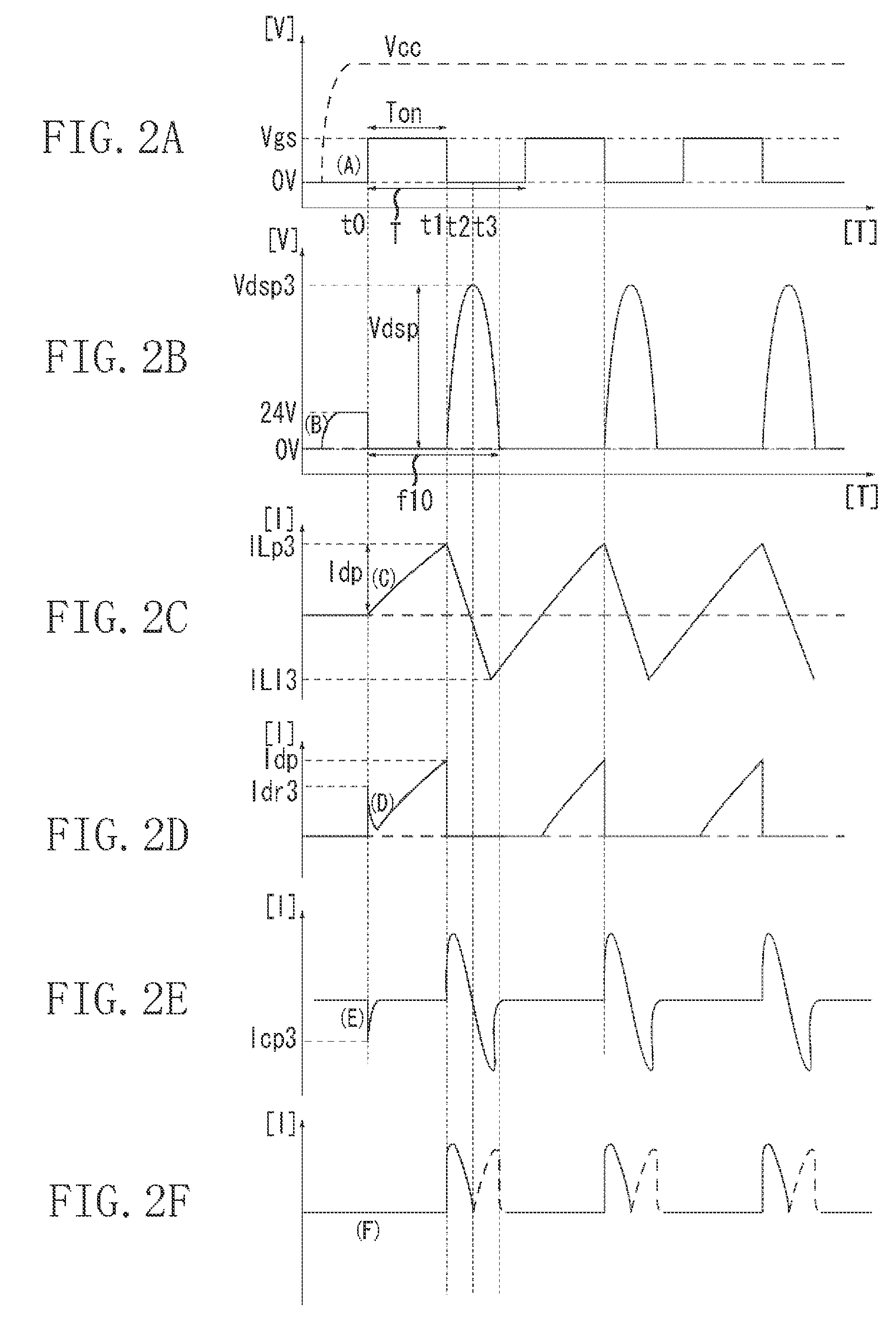
Further, the surge current not only deteriorates the conductive rubber, but also becomes a factor responsible for eventually degrading a peak value of a drive voltage for driving the piezoelectric transformer.

Method used


Image

  • Power supply apparatus and image forming apparatus
  • Power supply apparatus and image forming apparatus
  • Power supply apparatus and image forming apparatus

Examples


Embodiment Construction

[0029]Various exemplary embodiments, features, and aspects of the invention will be described in detail below with reference to the drawings.

[0030]Hereinbelow, a configuration, and an operation of a power supply apparatus that outputs a high-voltage using a piezoelectric transformer, which is a prerequisite to the present invention, will be described. After describing the prerequisite configuration and operation, exemplary embodiments will be described. It is to be noted that exemplary embodiments illustrated below are just examples, and it is not intended to limit a technical scope of the invention only to these exemplary embodiments.

[0031]FIG. 6 illustrates a prerequisite configuration of a power supply apparatus that outputs a high-voltage using a piezoelectric transformer. The prerequisite configuration is a configuration before countermeasures are taken against the above-described surge current.

[0032]In FIG. 6, a high-voltage output control signal (hereinafter, referred to as V...


PUM


Abstract

A power supply apparatus including a current regulation unit configured to regulate a surge current generated on a primary side of a piezoelectric transformer. The surge current is generated when the piezoelectric transformer including a piezoelectric element and a holding unit, which are connected to each other using a conductive rubber, is driven.

Description

BACKGROUND OF THE INVENTION[0001]1. Field of the Invention[0002]The present invention relates to a power supply that outputs a high-voltage using a piezoelectric transformer.[0003]2. Description of the Related Art[0004]In an image forming apparatus using an electrophotographic process, an image formed on a photosensitive member (image bearing member) is transferred on a recording material thereby forming the image on the recording material. In order to transfer the image onto the recording material, the image formed on the photosensitive member is transferred to the recording material by applying a direct current (DC) high-voltage on a transfer roller (transfer member). In order to satisfactorily transfer the image formed on the photosensitive member to the recording material, it is necessary to apply a high-voltage of a several kV or over.[0005]As a power supply apparatus for such a high-voltage output, conventionally a wire-wound electromagnetic transformer has been used. However,...

Claims


Application Information

Patent Timeline
Patent Type & Authority Patents(United States)
IPC IPC(8): G03G15/00
CPCG03G15/80H02M3/335H01L41/044G03G15/0283H10N30/804
Inventor NEMOTO, KENJI
Owner CANON KK
Why Eureka
Try Eureka