Internal combustion engine

a combustion engine and internal combustion technology, applied in the field of engines, can solve the problems of loss of energy efficiency, reliability and manufacturing cost reduction, efficiency and reliability, etc., and achieve the effect of simple, efficient and reliabl

Active Publication Date: 2014-02-04
DAOUK ANTAR
View PDF17 Cites 3 Cited by
  • Summary
  • Abstract
  • Description
  • Claims
  • Application Information

AI Technical Summary

Benefits of technology

[0011]One object of the invention is consequently to provide remedies to the various drawbacks mentioned above and to provide a novel engine having an architecture which is particularly simple, efficient and reliable.
[0012]Another object of the invention is to provide a novel engine which employs a minimal number of moving parts, which is particularly reliable and which has small dimensions, in particular in the height and width directions.
[0013]Another object of the invention is to provide a novel engine employing a mechanical link between the pistons and the output shaft, which, is not only particularly simple, efficient and reliable but also allows the performance of the engine to be easily and rapidly adjusted.
[0015]Another object of the invention is to provide a novel engine which is particularly compact and avoids the use of off-axis load transfers and offset transmission parts.
[0016]Another object of the invention is to provide a novel engine capable of performing the intake stroke and the exhaust stroke particularly efficiently.

Problems solved by technology

Firstly, the presence of a cylinder head fastened to the cylinder is likely to entail reliability problems, in particular at the cylinder head gasket interposed between the cylinder and the cylinder head. The use of a cylinder head and the corresponding gasket necessarily limits the compression ratio of the engine, since a high or very high compression ratio could of course damage the cylinder head gasket. Moreover, these known engines employ a relatively heavy and complex, mechanical and kinematic, chain for off-axis load transfer between the crankshaft, the camshaft (which is generally offset) and the valves. This of course constitutes a potential source of failure and loss of energy efficiency, and goes counter to both increased reliability and manufacturing cost reduction.
In general, these known engines employ a large number of moving parts, corresponding to a high moving mass, liable here again to cause efficiency and reliability problems.
Moreover, the architecture of these known engines is relatively constricting from the point of view of intake and exhaust cross sections, which are limited to relatively small values because of the constraints on fitting the valves into the cylinder head.
Finally, these known engines also prove to be relatively heavy and bulky, so that fitting them into an automobile, particularly an automobile of the passenger car type, may prove to be problematic.

Method used


Image

  • Internal combustion engine
  • Internal combustion engine
  • Internal combustion engine

Examples


Embodiment Construction

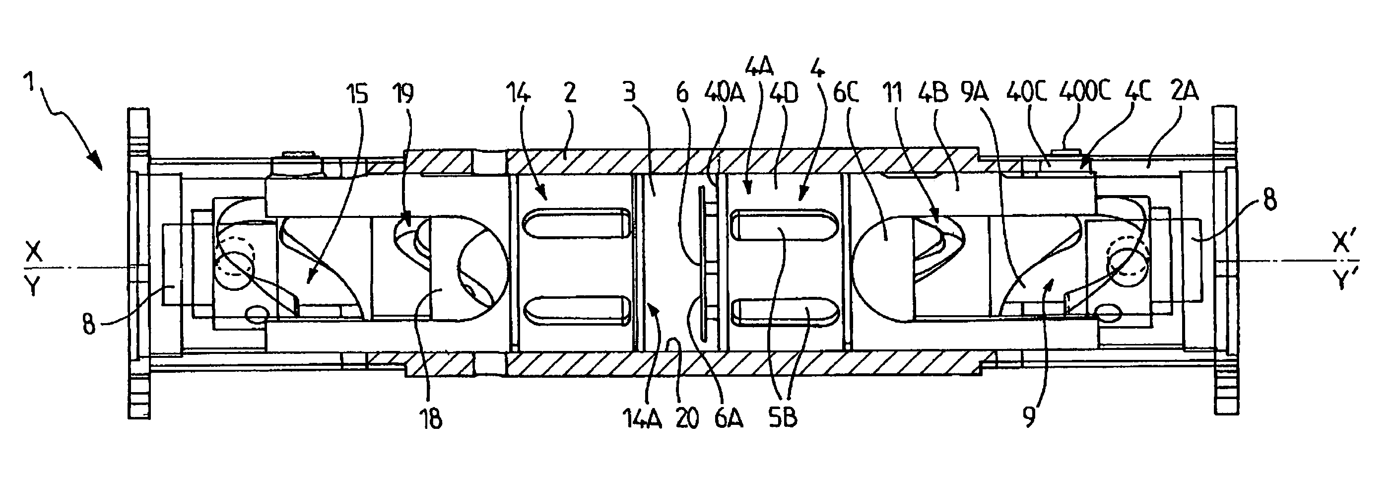
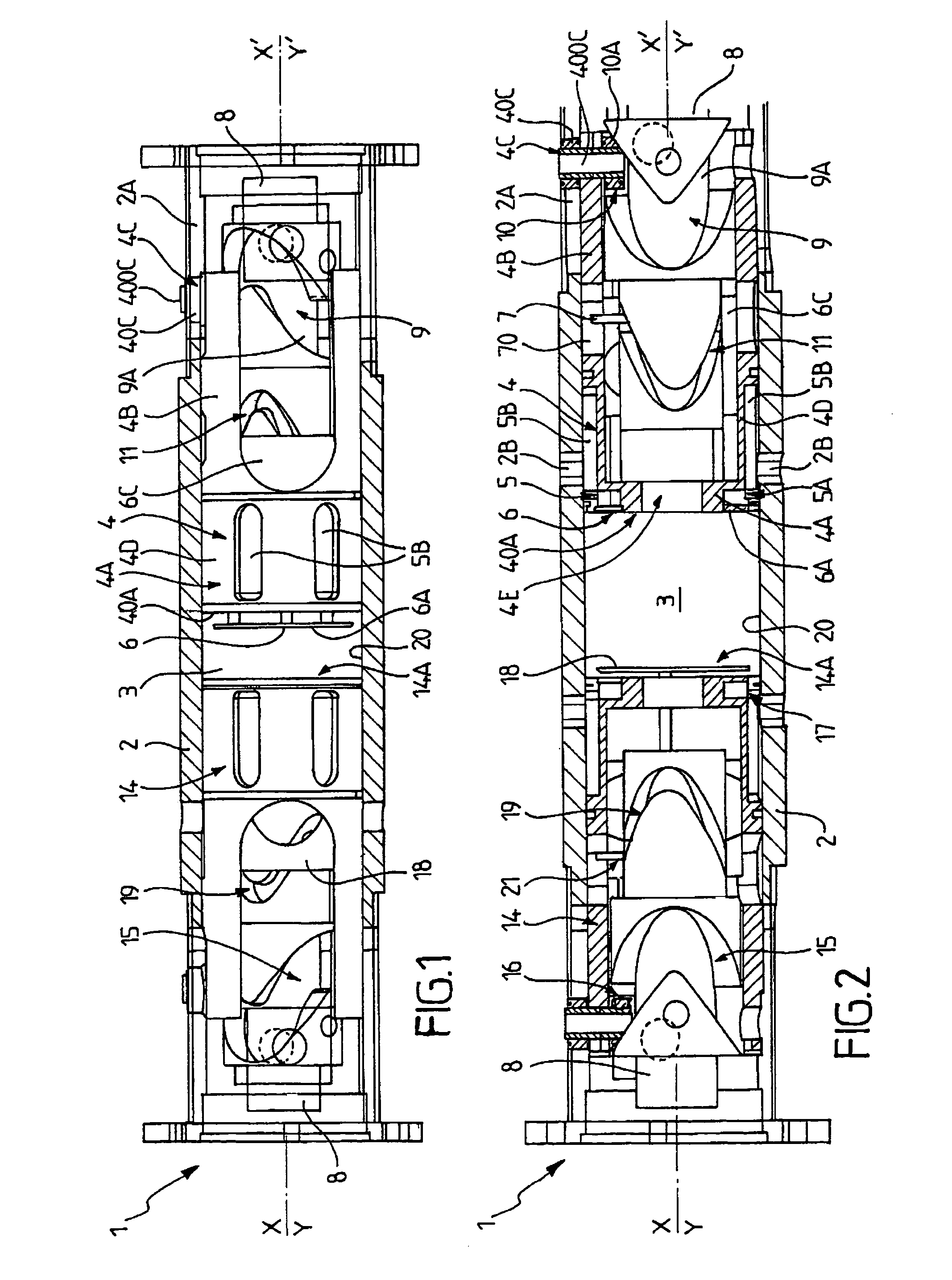
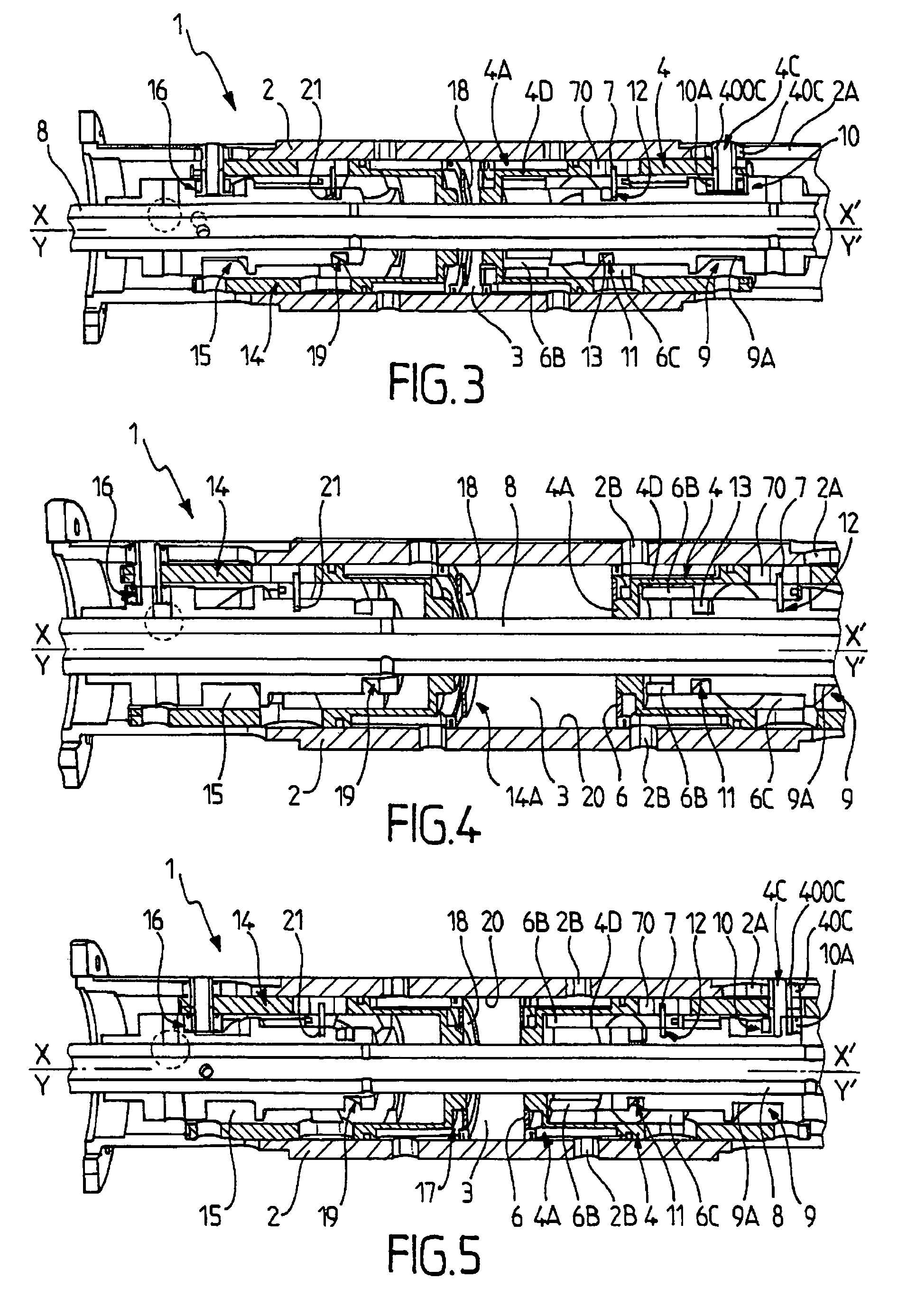
[0040]The invention relates to an engine, that is to say a device capable of delivering mechanical work that can be used especially to propel a vehicle, for example an automobile, a motorcycle, an aircraft or a ship, or to operate a machine (a machine tool, civil engineering machinery, agricultural machinery, a pump, or a compressor) or an energy conversion device, such as a generator. The engine 1 according to the invention is an internal combustion engine, that is to say an engine capable of producing mechanical energy from the combustion within it of a working fluid containing a fuel, for example a hydrocarbon-based fuel such as gasoline. In a manner known per se, the engine 1 according to the invention comprises a chamber 3, forming a combustion chamber and designed for this purpose to receive a working fluid intended to undergo combustion within said chamber 3. The working fluid is therefore a combustible fluid and is preferably formed from a gas consisting of a mixture of air ...


PUM


Abstract

The invention relates to an engine (1) including: —a chamber (3) designed to accommodate a working fluid, —a first piston (4) defining the volume of said chamber (3), —a first passage (5) located in said first piston (4) to supply the chamber (3) with working fluid and / or to discharge from the chamber (3) the burned fluid resulting from the combustion of the working fluid, —a first valve (6) mounted on the first piston (4) to monitor the opening and closing of said first passage (5), —an output shaft (8) that engages with the first piston (4) to convert the motion of the first piston (4) into rotational motion of the output shaft (8), characterized in that the output shaft (8) and the first valve (6) engage to convert the motion of output shaft (8) into motion of the first valve (6).

Description

[0001]This application is a §371 national stage of PCT International Application No. PCT / FR2009 / 050440, filed Mar. 17, 2009, claiming priority of French Patent Application No. 0801436, filed Mar. 17, 2008, the contents of all of which are hereby incorporated by reference into this application.TECHNICAL FIELD[0002]The present invention relates to the general technical field of engines, and in particular to internal combustion engines, which convert the thermal energy obtained by combustion, inside the engine itself, of a working fluid into mechanical energy that can be used, for example, to propel vehicles (such as automobiles, motorcycles, aircraft or ships), to drive machines (industrial or agricultural machinery) or to deliver mechanical energy to energy conversion devices of the electric power generator type.[0003]The invention relates more precisely to an internal combustion engine comprising, on the one hand, a chamber designed to receive a working fluid intended to undergo com...

Claims


Application Information

Patent Timeline
Patent Type & Authority Patents(United States)
IPC IPC(8): F02B75/28
CPCF01B1/01F01L1/30F02B75/282F01B3/04F01L11/02F01B9/06F01B7/02F02B75/28
Inventor DAOUK, ANTAR
Owner DAOUK ANTAR
Why Eureka
Try Eureka