Propulsion device for automobile with portal axle comprising an electrical machine

a technology of propeller device and automobile, which is applied in the direction of electric vehicles, vehicle sub-unit features, toothed gearings, etc., can solve the problems of rigid axle shape, and achieve the effects of reducing excessive torque, reducing consumption, and increasing vehicle power

Active Publication Date: 2014-02-04
DR ING H C F PORSCHE AG
View PDF109 Cites 55 Cited by
  • Summary
  • Abstract
  • Description
  • Claims
  • Application Information

AI Technical Summary

Benefits of technology

[0012]The force-fitting connection between the step-down gear mechanism and the wheel which is associated with said step-down gear mechanism by means of the cardan shaft allows torques to be transmitted without the need for the axle to be rigid. Consequently, the motor vehicle which is provided with the drive apparatus can, in contrast to the motor vehicles according to the discussed prior art, be provided with an independent suspension system. This considerably expands the field of use for the drive apparatus, in particular to cars in which it is advantageous, for reasons of driving comfort and driving safety, if each wheel can undergo spring compression and spring extension individually, that is to say independently of the other wheels of the vehicle.
[0014]The radial offset of the portal axle and the axle of the wheel scar is preferably compensated for by the step-down gear mechanism being in the form of a spur gear stage. It is considered to be particularly advantageous if a planetary gear mechanism is arranged between the respective electrical machine and the spur gear stage which faces said electrical machine. By virtue of this gear mechanism design between the electrical machine and the wheel which is associated with said electrical machine, it is possible to transmit a particularly high torque to the wheel, but with the maximum speed which can be reached being reduced.
[0018]It is also considered advantageous if a torque sensor is provided for detecting the torque in the drive train of the respective wheel. As a result, it is possible to individually activate the respective electric drive in accordance with the desired torque which is to be introduced by means of the respective wheel.
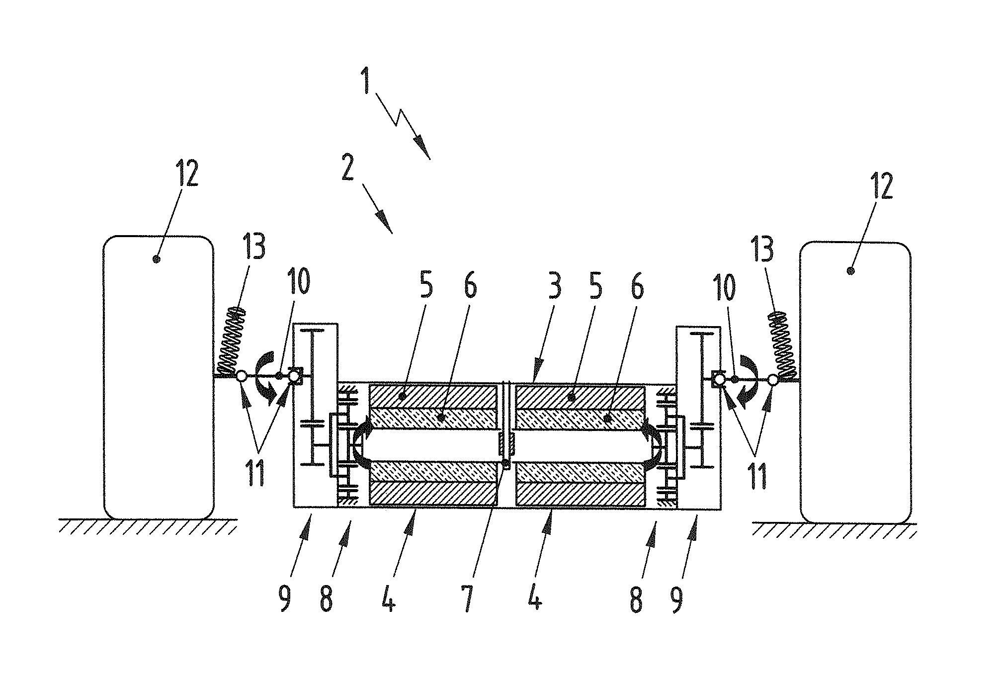
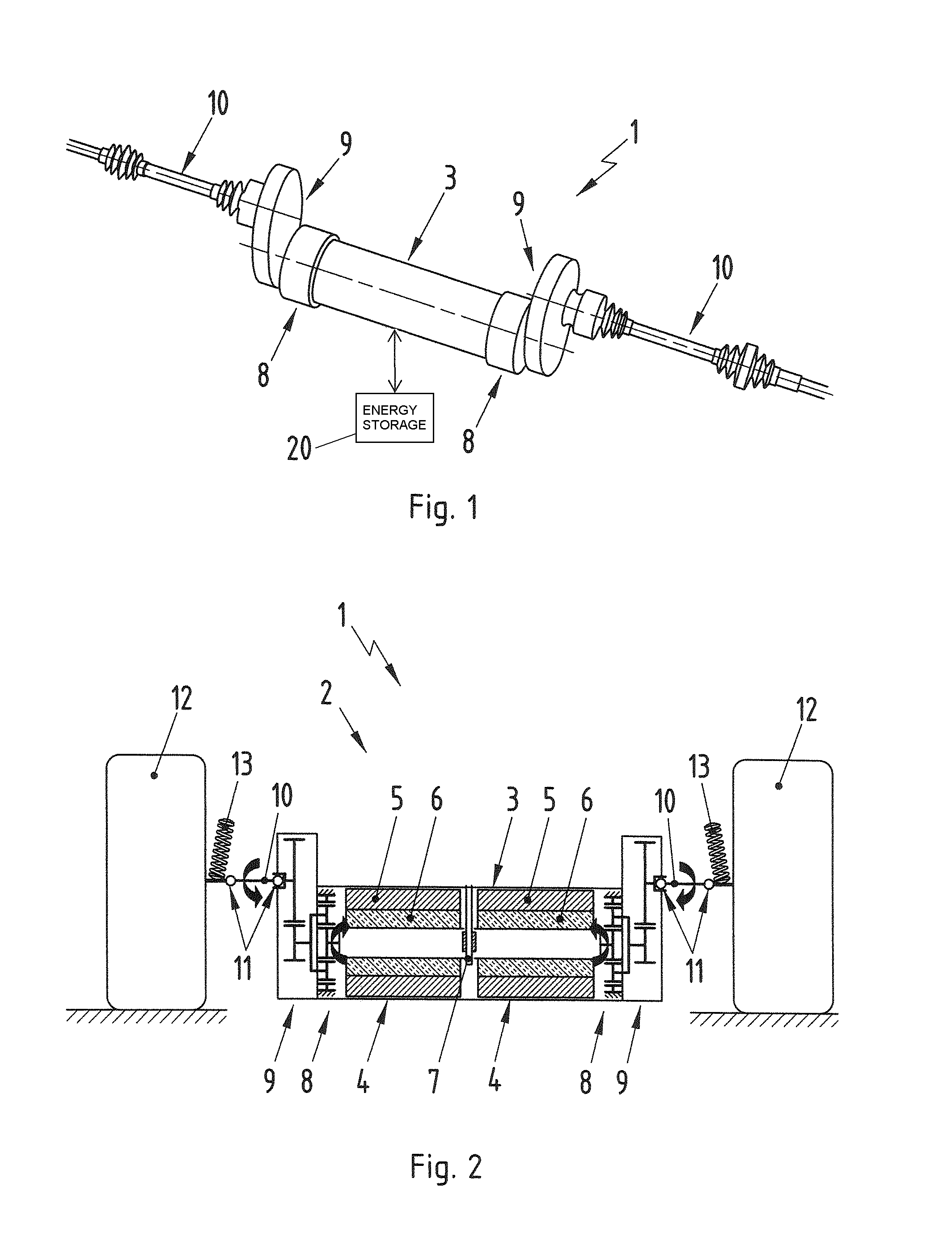
[0021]The drive apparatus according to the invention is therefore used, in particular, in a vehicle which can be driven by means of a hybrid drive. The hybrid system serves to increase the vehicle power and reduce consumption, in particular in a sports car, by adding the additional electrical drive machines and the energy storage means. A positive or negative torque, which is specific to the wheel, can be impressed on the drive shafts at the front axle of the motor vehicle by means of the two electrical machines. The vehicle is accelerated (motor mode) or decelerated (generator mode) by operating the electrical machines. The energy storage means is discharged or charged in the process. It is important that there is no mechanical coupling between the torques of the electrical machines.
[0022]The function of the portal axis is to transmit the torque which is provided by the electrical machines to the front wheels of the vehicle by means of a suitable step-down means. To this end, a two-stage gear mechanism comprising a planetary gear stage and a spur gear stage, is in each case flange-connected to the output shafts of the electrical machines. The output shafts of the gear mechanism are connected directly to the wheels by means of cardan shafts. In this case, a separable clutch can be provided for emergencies. Therefore, a multiple-disk clutch can be formed in the step-down gear mechanism between the annulus gear and the housing. Said clutch is closed in the event of non-operation and can be hydraulically opened. Said clutch serves firstly as a safety function, so that the electrical machines can be mechanically disconnected from the wheels, for example in the event of a short circuit, and secondly acts as a component protection means. If a high torque is impressed on the drive side such that the gear mechanism or the drive shafts could be damaged, the clutch slips in order to reduce the excessive torque. The slip moment is set by the spring parameters of the contact-pressure springs which provide the clutch with a defined pretension. The gear mechanism transmission ratios allow a significant increase in the maximum torque which can be transmitted by means of the portal axle. Therefore, the torque which is produced at the respective wheel can be readily multiplied, for example by a factor of 6 to 8.

Problems solved by technology

One disadvantage of the described drive apparatuses or axle designs is, in particular if these designs relate to a portal axle, that they are in the form of rigid axles.

Method used


Image

  • Propulsion device for automobile with portal axle comprising an electrical machine
  • Propulsion device for automobile with portal axle comprising an electrical machine

Examples


Embodiment Construction

[0028]The motor vehicle which is equipped with the drive apparatus according to the invention is, in particular, a car which is intended to be used in racing and of which the individually suspended wheels which are associated with the rear axle are driven by means of an internal combustion engine and of which the wheels which are associated with the front axle and are likewise individually suspended can be driven by electric motor, for example in order to apply an additional drive torque by means of the front wheels. The following description relates to the design of the motor vehicle in the region of the front axle and the drive apparatus formed according to the invention in this respect. This drive apparatus 1 has a portal axle 2 with a central housing 3 which is in the form of a tube. Said housing serves to accommodate two electrical machines 4. The stator 5 of the respective machine 4 is mounted in a rotationally fixed manner in the housing 3, this housing 3 having the function ...


PUM


Abstract

A drive apparatus (1) for a motor vehicle has a hollow portal axle (2) that accommodates two electrical machines (4). Wheels (12) are mounted rotatably at opposite ends of the portal axle (2) and can be driven by the electrical machine (4) associated with the respective wheel. A step-down gear mechanism (8, 9) is arranged between each electrical machine (4) and the respective wheel (12) and a separate connection from the respective wheel to the step-down gear mechanism, permits the wheel to be mounted in a non-rigid manner. The respective step-down gear mechanism (8, 9) is connected to the respective wheel (12) by a cardan shaft (10).

Description

BACKGROUND OF THE INVENTION[0001]1. Field of the Invention[0002]The invention relates to a drive apparatus for a motor vehicle, having a hollow portal axle which accommodates two electrical machines, within each case one wheel being rotatably mounted in the region of the two ends of the portal axle and it being possible for each wheel to be driven only by means of the electrical machine which is associated with said wheel, and having a step-down gear mechanism which is arranged between the respective electrical machine and the wheel which is associated with said electrical machine.[0003]2. Description of the Related Art[0004]A drive apparatus of this kind, which is used in a utility vehicle, is known from DE 295 18 401 U1. This utility vehicle is a city bus for transporting people. In city buses, a carriage floor which is arranged at a low level and runs through the entire bus is required, in particular in the region of the rear axle which is in the form of a rigid axle. In order to...

Claims


Application Information

Patent Timeline
Patent Type & Authority Patents(United States)
IPC IPC(8): B60K1/02
CPCB60K17/046B60K7/0007B60L2220/46B60K2007/0046B60K2007/0061Y02T10/7258B60Y2410/10Y02T10/72B60K6/00B60K6/22B60K6/26B60K6/42B60K6/485B60K6/52B60K7/00F16H1/32
Inventor HENNINGS, STEPHANARMBRUSTER, DANIELSCHMID, JOCHEN
Owner DR ING H C F PORSCHE AG
Why Eureka
Try Eureka