Animal waste collection apparatus and method of use

a technology for collecting apparatus and animal waste, which is applied in the direction of hoisting equipment, transportation and packaging, road cleaning, etc., can solve the problems of inconvenient and distasteful animal waste, and the device does not provide a housing that allows, so as to achieve convenient use and economical manufacturing

Inactive Publication Date: 2014-02-04
SURBER EDWARD +1
View PDF10 Cites 0 Cited by
  • Summary
  • Abstract
  • Description
  • Claims
  • Application Information

AI Technical Summary

Benefits of technology

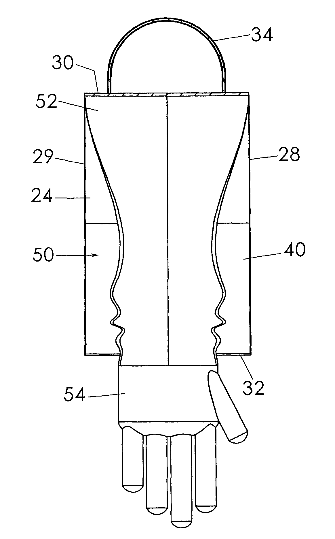
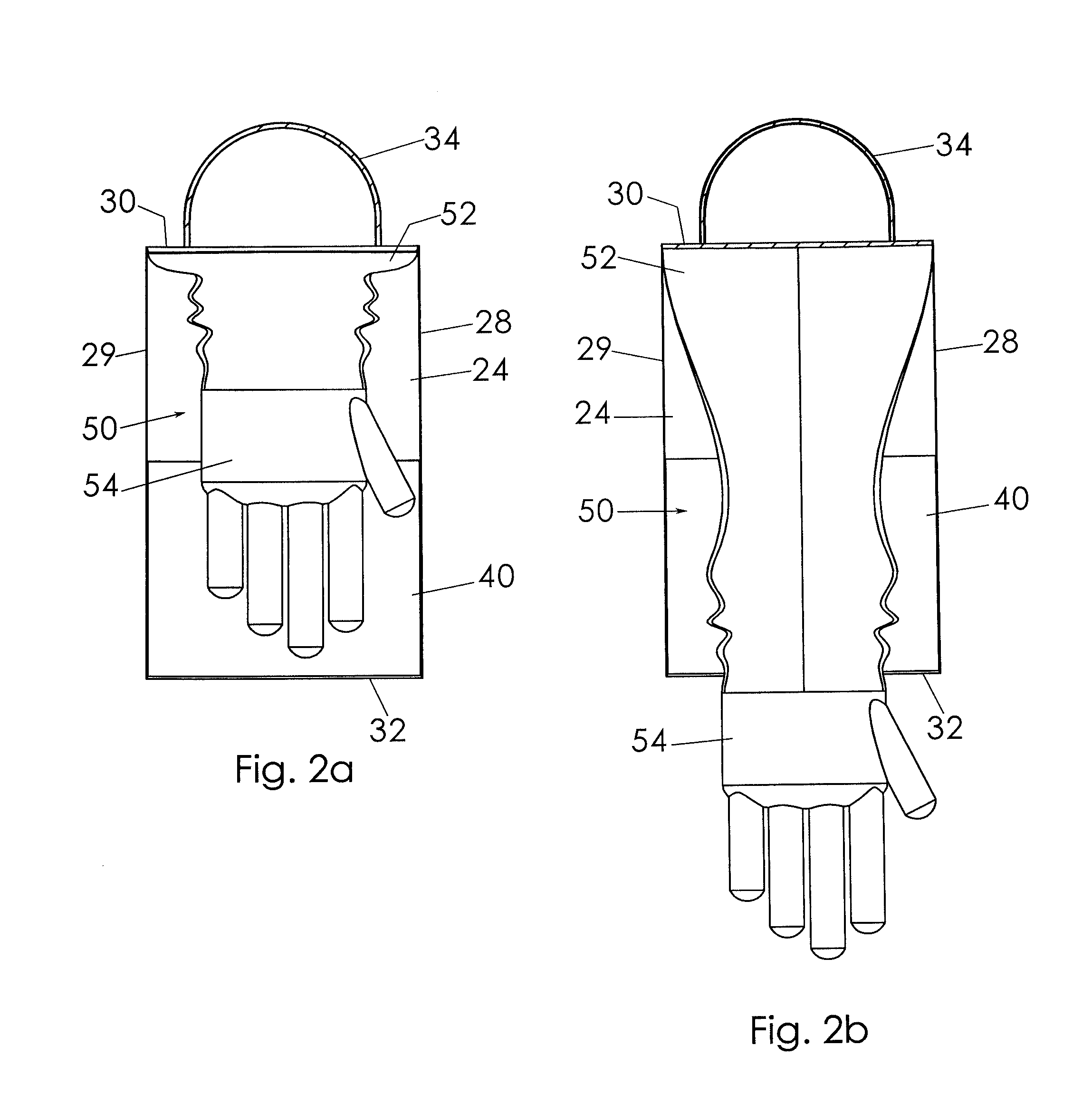
[0006]A collection member includes a mounting portion connected to an upper end of the housing and a collection portion extending downwardly from the mounting portion into the housing interior area, the collection portion being resiliently movable between a retracted configuration inside the housing interior area and an extended configuration extending outside the housing interior area through the open bottom so as to selectively capture animal waste. The bottom panel is operatively coupled to the collection portion such that the bottom panel is moved to the closed configuration when the collection portion resiliently moves from the extended configuration to the retracted configuration. A user is then able to release the animal waste to rest on top of the bottom panel and remove his hand from the collection / glove portion. At that point, the waste is contained inside the housing and may be conveniently and cleanly disposed of.
[0010]Yet another object of this invention is to provide a waste collection apparatus and method, as aforesaid, that is easy to use and economical to manufacture.

Problems solved by technology

Performing this task of collecting and disposing of animal waste is considered both inconvenient and distasteful.
Although assumably effective for their intended purposes, the existing devices do not provide a housing that enables easy collection of animal waste into a container without any risk of physical contact with it and that automatically seals after the waste is deposited therein.

Method used


Image

  • Animal waste collection apparatus and method of use
  • Animal waste collection apparatus and method of use
  • Animal waste collection apparatus and method of use

Examples


Embodiment Construction

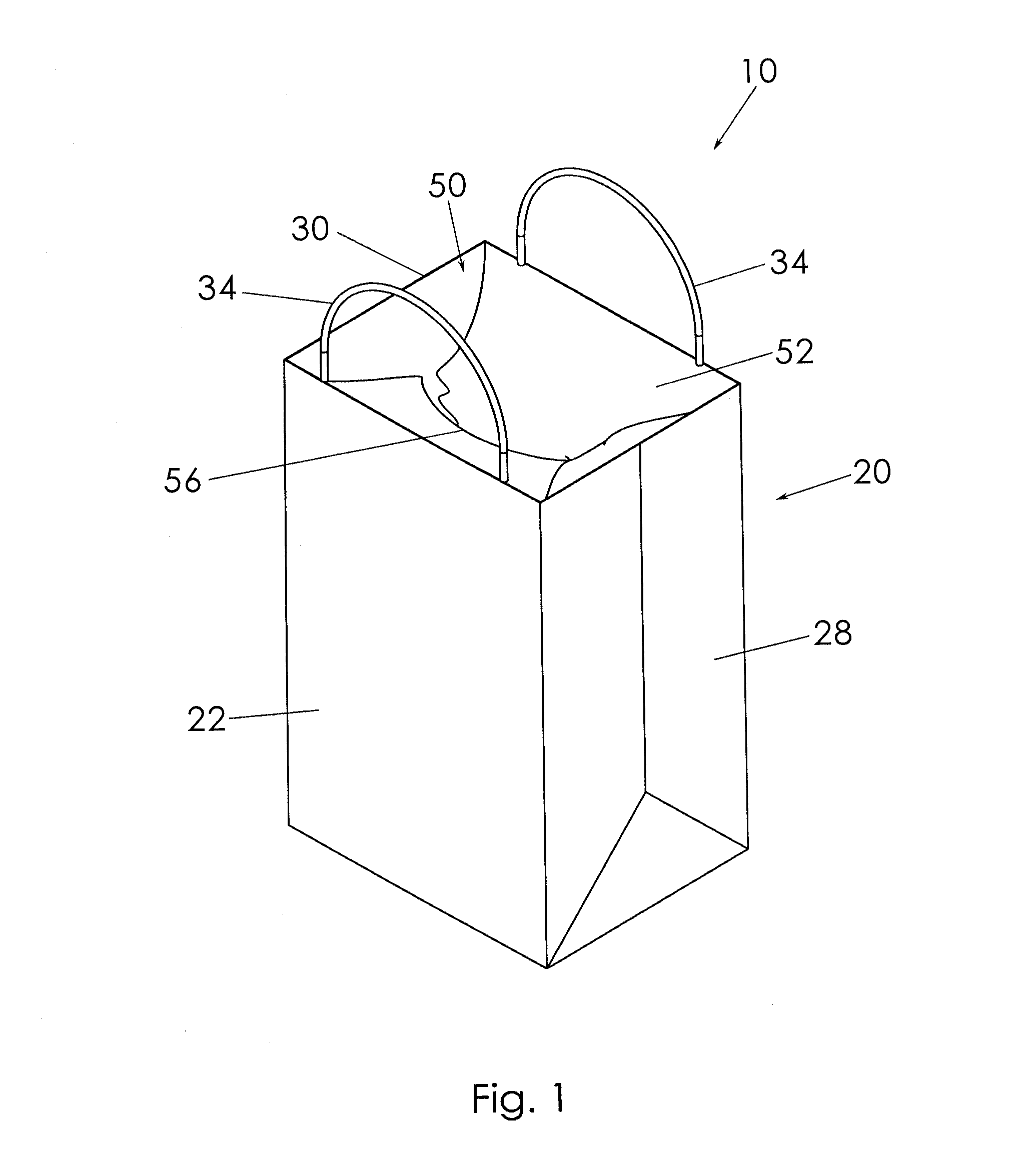
[0025]A waste collection apparatus and method will now be described with reference to FIGS. 1 to 9b of the accompanying drawings. The waste collection apparatus 10 includes a housing 20, a bottom panel 40, and a collection portion 54.

[0026]The housing 20 includes opposed first 22 and second 24 side walls and opposed first 28 and second 29 end walls extending between respective lateral edges of respective side walls. Upper edges of respective walls define an open top 30. Lower edges of respective walls define an open bottom 32. The housing 20 is configured to be moved selectively between a collapsed or generally flat configuration (not shown) and an expanded configuration (FIG. 1). It is apparent that the housing 20 may be maintained in the collapsed configuration when not in use, such as when packaged for sale and for storage before use and then be expanded when ready for use in collecting animal waste as will be described in more detail later. The housing side and end walls may be ...


PUM


Abstract

An animal waste collection apparatus includes a housing having side and end walls defining an open top, bottom, and interior area. A bottom panel is pivotally coupled to a lower edge of one of the side walls and movable between an open configuration not covering the open bottom and a closed configuration covering the open bottom. A collection member includes a mounting portion completely covering the housing open top and a collection portion extending downwardly into the interior area, the collection portion being movable between a retracted configuration inside the interior area and an extended configuration outside the interior area through the open bottom for use to collect animal waste. The bottom panel is operatively coupled to the collection portion inside the interior area such that the bottom panel is moved to the closed configuration automatically when the collection portion resiliently moves from the extended configuration to the retracted configuration.

Description

BACKGROUND OF THE INVENTION[0001]The present invention relates generally to animal waste collection devices and, more particularly, to a waste collection apparatus having an impermeable membrane that is selectively extendable outside a housing to collect waste and then retractable to deposit the waste inside the automatically sealed housing.[0002]A common daily task for a dog owner is either to let the dog outside of a house into the backyard or to walk the dog on a leash so that the dog may have a bowel movement outside the house. In either case, the pet owner feels a responsibility (or in some cases a legal mandate) to pick up the waste and dispose of it. Performing this task of collecting and disposing of animal waste is considered both inconvenient and distasteful.[0003]Various devices have been proposed in the art for collecting animal waste without having to simplify the task of collecting the waste, to improve the means for disposing of it, or even to avoid any physical conta...

Claims


Application Information

Patent Timeline
Patent Type & Authority Patents(United States)
IPC IPC(8): A01K29/00E01H1/12
CPCE01H1/1206E01H2001/124A01K29/00
Inventor SURBER, EDWARDDEVORAK, ERIC
Owner SURBER EDWARD
Why Eureka
Try Eureka