AI technical title is built by PatSnap AI team. It summarizes the technical point description of the patent document.
a key switch and link technology, applied in the direction of contact mechanisms, mechanical control devices, instruments, etc., can solve problems such as difficulty in assembling keyboards
Active Publication Date: 2014-02-04
JIANGSU TRANSIMAGE TECH CO LTD
View PDF6 Cites 43 Cited by
Summary
Abstract
Description
Claims
Application Information
AI Technical Summary
This helps you quickly interpret patents by identifying the three key elements:
Problems solved by technology
Method used
Benefits of technology
Benefits of technology
The patent describes a link structure and key switch that are designed to be easy to assemble. The link member can be elastically deformed based on pressure applied to the first inclined surfaces, which increases the distance between shaft holes and between first stopper members. This allows for easy assembly of the link structure.
Problems solved by technology
The link structures may include rotating members that present difficulties in assembling the keyboards.
Method used
Image
Click on the blue label to locate the original text in one second.
Reading with bidirectional positioning of images and text.
Examples
first embodiment
[0042
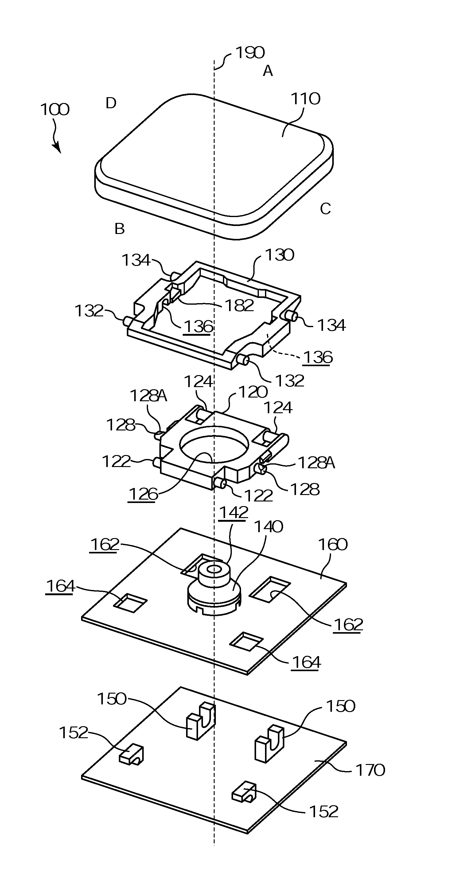
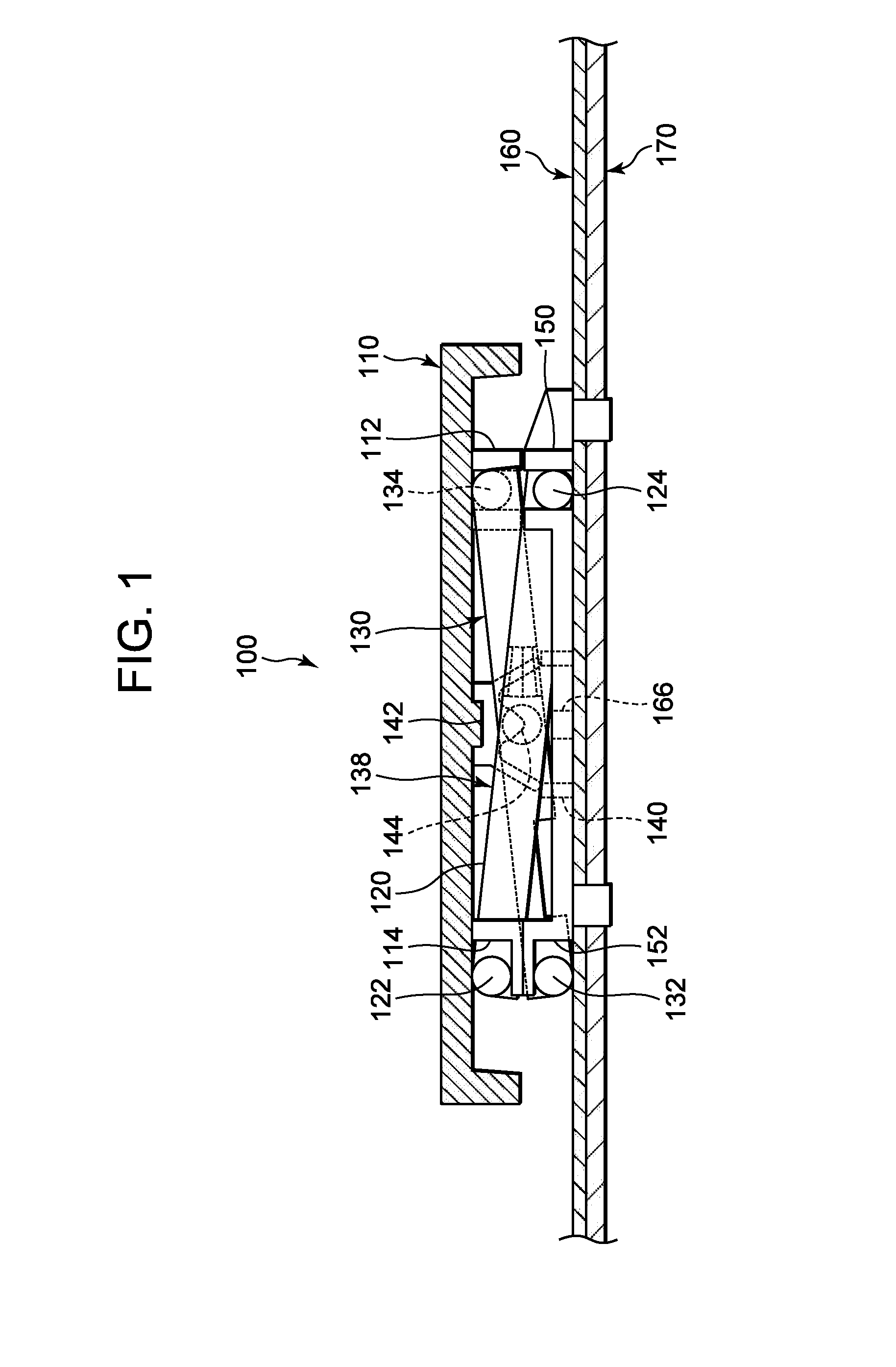
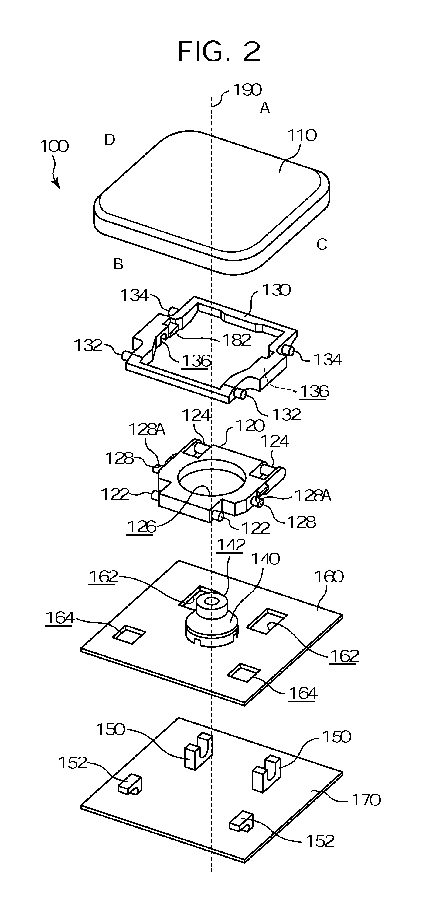
[0043]FIG. 1 is a cross-sectional view of a key switch structure 100 according to a first embodiment. FIG. 2 is a first exploded perspective view of the key switch structure 100 shown in FIG. 1. In FIG. 2, there are four letters (A, B, C, and D) to support explanations of the embodiment. The letters A, B, C, and D represent respectively the right upper side, the left under side, the right under side, and the left under side of respective members shown in FIG. 2. Also, these letters will be used in FIGS. 3, 4, 5, 6, 11, 12, 13, and 14 as with FIG. 2.
[0044]Referring to FIGS. 1 and 2, the key switch structure 100 can include a key top 110, an inside link member 120, an outside link member 130, a dome 140 which can be or include an elastic, e.g., rubber, member, a membrane sheet 160, and a back plate 170. As shown in FIG. 2, only one section of the membrane sheet 160 and the back plate 170 corresponding to the key top 110 is illustrated. However, when the key top structure is actua...
second embodiment
[0084
[0085]Next, a second embodiment will be described. Elements identical to those of the first embodiment will be designated by the same reference numbers, and results based on inclusion of the identical elements will be incorporated herein by reference.
[0086]FIG. 13 is a perspective view of an inside link member according to the second embodiment. FIG. 14 is a perspective view of an outside link member according to the second embodiment. As shown in FIGS. 13 and 14, the shape of the inside and outside link members 320 and 330 can be different from those of the first embodiment.
[0087]The inside link member 320 can have two shaft holes 336 formed therein, and can include two stopper members 382 instead of the link rotational shafts 128 and the stopper members 180. The shaft hole 336 can have an inserting groove 336A formed on a surface thereof, and include two chamfered portions 337A and 337B. The shaft hole 336, the stopper member 382, the inserting groove 336A, and the chamfered ...
PUM
Abstract
A link structure can include an outside link member and an inside link member. Shaft holes can be formed in respective inner lateral sides of the outside link member and face each other across a first opening portion. First stopper members can be arranged on the respective inner lateral sides, and each have a first inclined face and a first stopper surface. The outside link member can be elastically deformable based on a pressure applied to the first inclined surfaces that increases a distance between the shaft holes. The inside link member can include a second opening portion, link rotational shafts that are disposed in the shaft holes, and second stopper members each having a second inclined surface and a second stopper surface. The inside link member can be elastically deformable based on a pressure applied to the second inclined surfaces that decreases a distance between the link rotational shafts.
Description
CROSS-REFERENCE TO RELATED APPLICATION[0001]This application claims priority under 35 U.S.C. §119 from Japanese Patent Application NO. P 2011-113583, filed on May 20, 2011, the disclosure of which is incorporated herein by reference.BACKGROUND[0002]1. Technical Field[0003]This application relates to a link structure and a key switch structure used for a keyboard of an apparatus, such as an information processing apparatus, a measuring apparatus, a medical apparatus, or a personal computer.[0004]2. Description of the Related Art[0005]Keyboards in apparatuses as described above conventionally include link structures. The link structures may include rotating members that present difficulties in assembling the keyboards.SUMMARY[0006]This application discloses aspects of a link structure and a key switch structure which assembly workers may assemble easily.[0007]According to one aspect, a link structure can include an outside link member, and an inside link member. The outside link membe...
Claims
Application Information
Patent Timeline
Application Date:The date an application was filed.
Publication Date:The date a patent or application was officially published.
First Publication Date:The earliest publication date of a patent with the same application number.
Issue Date:Publication date of the patent grant document.
PCT Entry Date:The Entry date of PCT National Phase.
Estimated Expiry Date:The statutory expiry date of a patent right according to the Patent Law, and it is the longest term of protection that the patent right can achieve without the termination of the patent right due to other reasons(Term extension factor has been taken into account ).
Invalid Date:Actual expiry date is based on effective date or publication date of legal transaction data of invalid patent.

