Liquid crystal display device having an outer-side optical member and a backlight-side optical member

a liquid crystal display device and optical member technology, applied in non-linear optics, instruments, optics, etc., can solve the problems of liquid crystal material and the like in the liquid crystal layer deteriorating, transmittance or color change deterioration, etc., to suppress the deterioration of liquid crystal material and suppress the deterioration of transmittance

Inactive Publication Date: 2014-02-04
SONY CORP
View PDF7 Cites 0 Cited by
  • Summary
  • Abstract
  • Description
  • Claims
  • Application Information

AI Technical Summary

Benefits of technology

[0009]The invention addresses the issue of providing a liquid crystal display device, which is capable of suppressing deterioration of the liquid crystal material and suppressing deterioration in transmittance, and an electronic apparatus having the same.
[0011]In the embodiment of the invention, the external light is incident from the one side substrate to the liquid crystal layer, and the light emitted from the light source is incident from the other side substrate to the liquid crystal layer. The light emitted from the light source includes a larger amount of light with the specific peak wavelength, in a region shorter than the wavelength of blue light in the visible light region as compared with the external light. The liquid crystal display device according to the embodiment of the invention suppresses transmission of the light with specific wavelength into the liquid crystal layer by absorbing the light with specific wavelength traveling from the outside of the other side substrate toward the liquid crystal layer.
[0016]According to the embodiments of the invention, it is possible to provide a liquid crystal display device, which is capable of suppressing deterioration of the liquid crystal material while suppressing the deterioration in transmittance, and an electronic apparatus having the same.

Problems solved by technology

For this reason, protection of the polarizer, the retarder, and the diffuser is sufficient, but a problem arises in that the liquid crystal material and the like in the liquid crystal layer deteriorates.
Further, although the cut wavelength of the ultraviolet absorber is easily extended to the long wavelength side, the light necessary for the liquid crystal display device is also absorbed, and thus this causes deterioration in transmittance or color change in the liquid crystal display device.

Method used


Image

  • Liquid crystal display device having an outer-side optical member and a backlight-side optical member
  • Liquid crystal display device having an outer-side optical member and a backlight-side optical member
  • Liquid crystal display device having an outer-side optical member and a backlight-side optical member

Examples


Embodiment Construction

[0026]Hereinafter, a mode for carrying out the invention (hereinafter referred to as an “embodiment”) will be described. In addition, the description will be given in order of the following items.

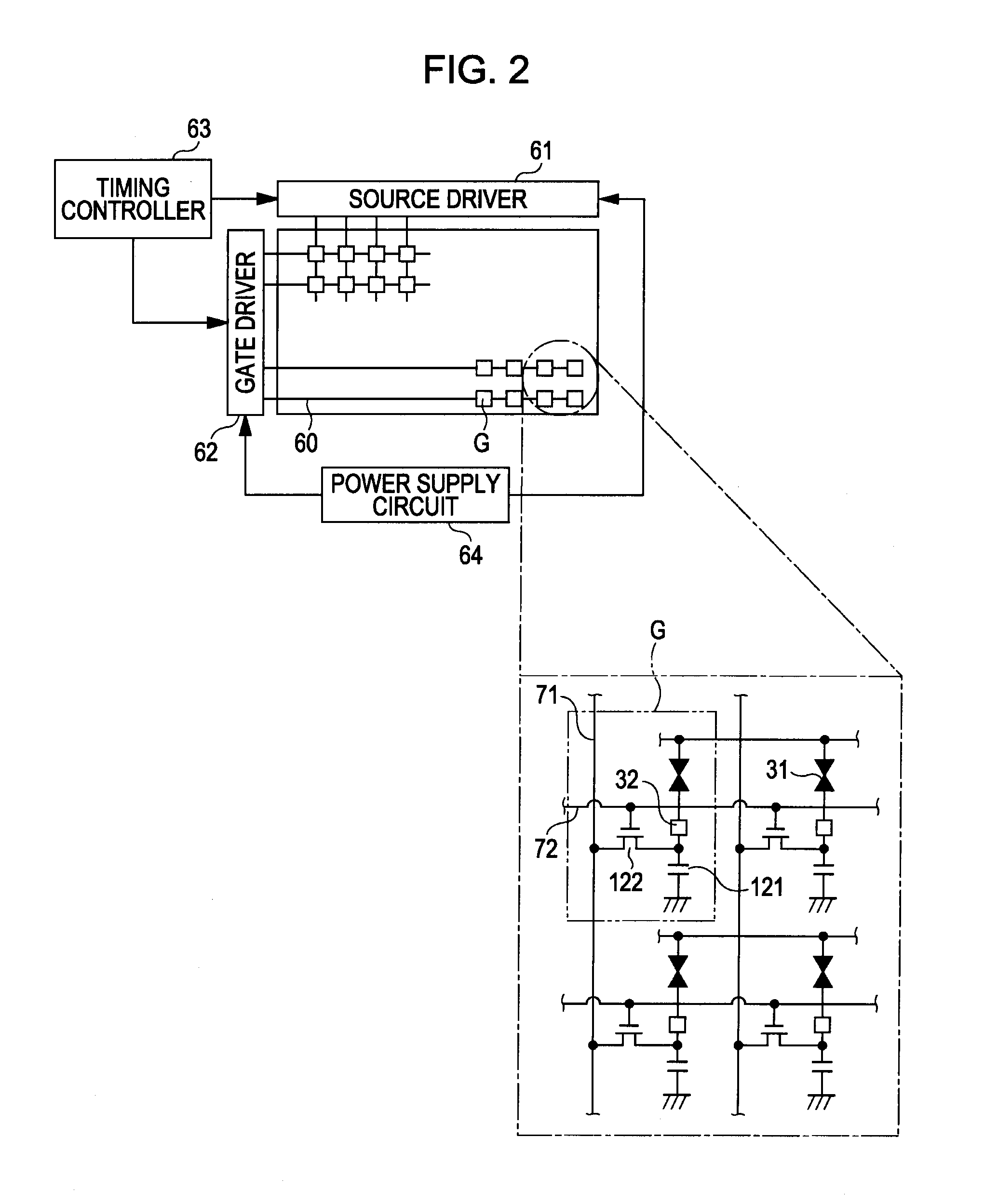
[0027]1. Liquid Crystal Display Device (Exemplary Configuration of Display Section, and Exemplary Configuration of Circuit)

[0028]2. Characteristics of Liquid Crystal Display Device of Embodiment (Summary of Characteristics, and Specific Example of Optical Member)

[0029]3. Reliability Evaluation (First Evaluation, and Second Evaluation)

[0030]4. Electronic Apparatus

1. Liquid Crystal Display Device

Configuration of Display Section

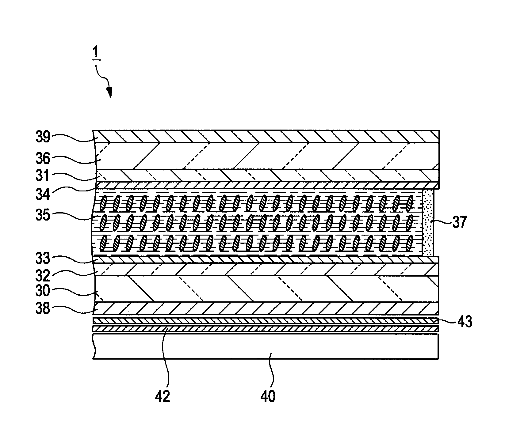
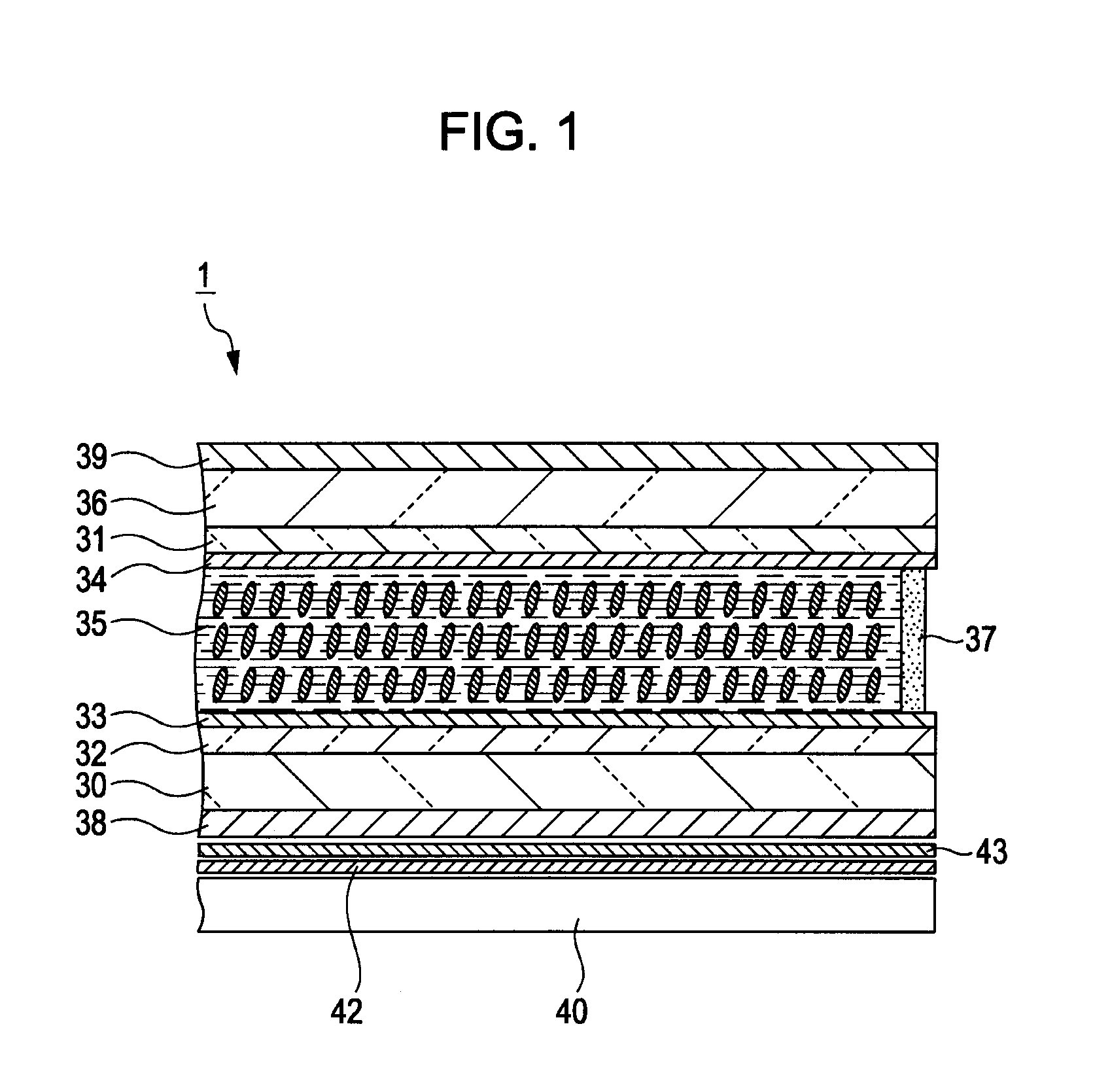
[0031]FIG. 1 is a schematic sectional view illustrating an exemplary configuration of a liquid crystal display device according to the embodiment. The liquid crystal display device 1 is configured as follows: a liquid crystal layer 35 is sandwiched between an upper substrate 36 of which the inner side has an electrode 31 and an alignment layer 34 formed thereon and a lo...


PUM

PropertyMeasurementUnit
peak wavelengthaaaaaaaaaa
cut wavelengthaaaaaaaaaa
wavelength of transmittanceaaaaaaaaaa

Abstract

A liquid crystal display device includes: one side substrate; the other side substrate that is disposed to be opposed to the one side substrate; a liquid crystal layer that is sandwiched between the one side substrate and the other side substrate; and a light source that illuminates light on the liquid crystal layer from the outside of the other side substrate. At a specific peak wavelength, in a region shorter than a wavelength of blue light in a visible light region of the light illuminated from the light source, a transmittance from the other side substrate to the liquid crystal layer is smaller than a transmittance from the one side substrate to the liquid crystal layer.

Description

BACKGROUND OF THE INVENTION[0001]1. Field of the Invention[0002]The present invention relates to a liquid crystal display device and an electronic apparatus. Specifically, the invention relates to a high-reliability and high-transmittance liquid crystal display device, which suppresses incidence of light unnecessary for a liquid crystal layer, and electronic apparatus having the same.[0003]2. Description of the Related Art[0004]In various display devices, liquid crystal display devices are lower-power consumption display devices which are thin in thickness and light in weight. Hence, the liquid crystal display devices are widely used in image display devices such as televisions, office automation equipment such as personal computers, and the like.[0005]In the liquid crystal display device, a liquid crystal cell is formed by sandwiching a liquid crystal layer between two glass substrates, of which the inner side has an electrode and an alignment layer formed thereon, and sealing the ...

Claims


Application Information

Patent Timeline
Patent Type & Authority Patents(United States)
IPC IPC(8): G02F1/1335
CPCG02F1/133504G02F2201/086G02F1/133528G02F1/133514G02F1/1335
Inventor SHIBAHARA, SEIJI
Owner SONY CORP
Why Eureka
Try Eureka