Dust seal for gyratory crusher

a gyratory crusher and dust seal technology, applied in the field of gyratory crushers, can solve the problems of lubricant loss, wear away the rubber skirt, and consumption of lubricant, and achieve the effects of less sensitive to variations in manufacturing tolerances and wear, and relatively easy to manufactur

Inactive Publication Date: 2014-02-11
SANDVIK INTELLECTUAL PROPERTY AB
View PDF19 Cites 3 Cited by
  • Summary
  • Abstract
  • Description
  • Claims
  • Application Information

AI Technical Summary

Benefits of technology

[0008]In another embodiment, the invention provides a dust seal for sealing a gap in a gyratory crusher between a frame and a fastening portion situated adjacent to a crusher head. The dust seal includes a seal bellows with a first end opening adapted to sealingly connect to a fastening portion situated close to the crusher head and a second end opening to which a seal slide ring is sealingly connected. The seal slide ring has a slide surface which faces away from the seal bellows and is adapted to slide along, and sealingly abut against, a slide surface provided on the frame. A guiding edge, which extends from the seal bellows, runs along the seal slide ring and is adapted to cooperate with a frame slide ring attached to the frame in order to limit transverse movements of the seal slide ring in the plane of the slide surfaces.
[0020]According to a further aspect, the problem is reduced by a method of fitting a dust seal to seal a gap in a gyratory crusher between a frame and a fastening portion situated close to a crusher head, by using a dust seal including a seal bellows and a seal slide ring which is connected sealingly to a lower portion of the seal bellows, which method includes providing torsionally secure tightness between an upper portion of the bellows and the fastening portion, so that the bellows and the seal slide ring are caused to accompany movements of the crusher head; providing sliding tightness between a lower slide surface provided on the seal slide ring and an upper slide surface provided on the frame; abutting the seal slide ring against the upper slide surface of the frame with a sealing force determined by the inherent weight of the seal slide ring and by the influence of the seal bellows; and guiding the seal slide ring so that it does not leave the upper slide surface of the frame. This ensures, during operation of the crusher, constant abutment between the slide surfaces, rendering the tightness of the dust seal less sensitive to variations in its manufacturing tolerances and amount of wear. The limited and self-regulating abutment pressure also results in limitation of the torsional forces to which the dust seal is subject.

Problems solved by technology

A problem with this sealing socket is that it involves lubricant loss.
Without lubrication, the frictional resistance between the sealing socket and the slide tube would wear away the rubber skirt in which the sealing socket is suspended.
The lubricant loss consumes lubricant and contaminates the material being crushed.
The dust seal is also expensive and relatively complicated to fit.

Method used


Image

  • Dust seal for gyratory crusher
  • Dust seal for gyratory crusher
  • Dust seal for gyratory crusher

Examples


Embodiment Construction

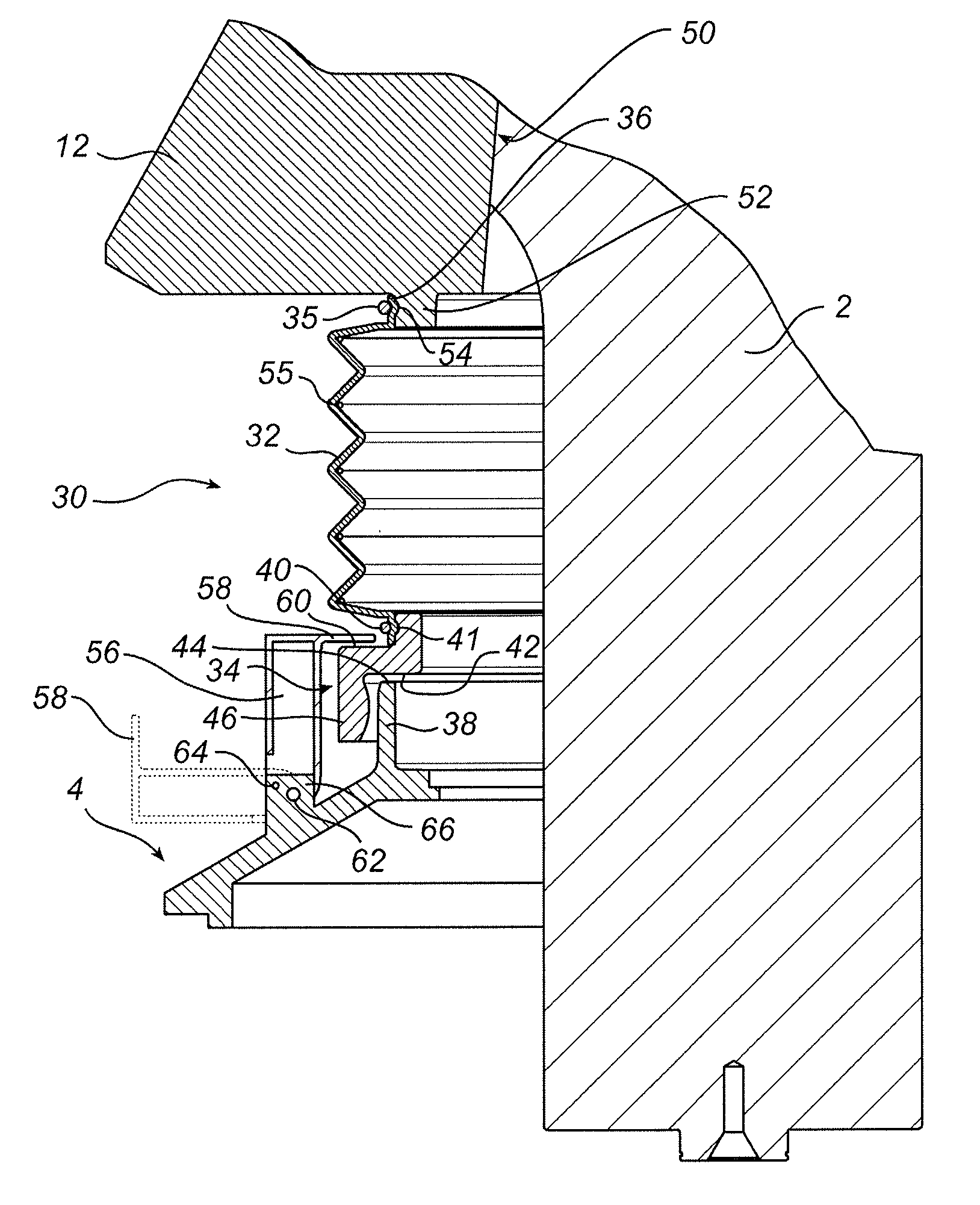
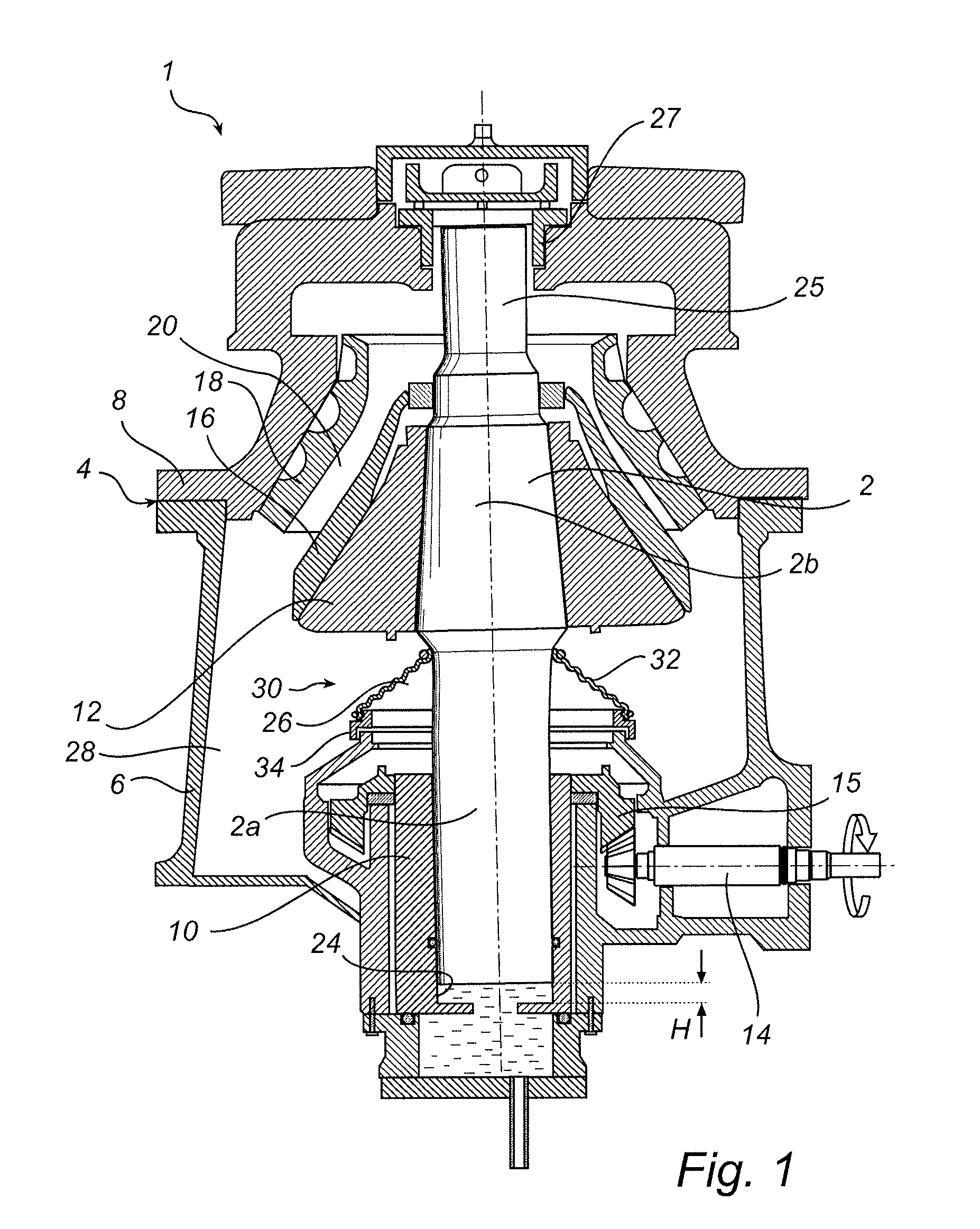
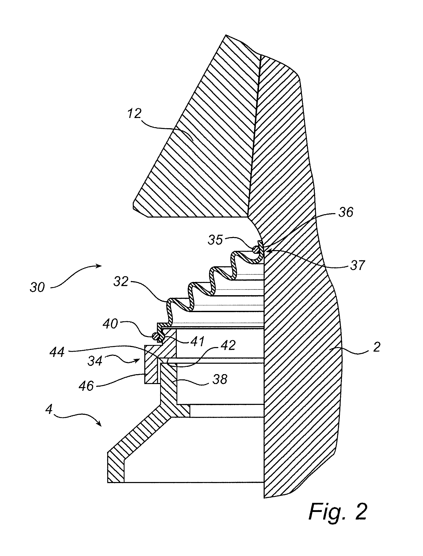
[0026]FIG. 1 illustrates schematically a gyratory crusher 1 according to a first embodiment. The gyratory crusher 1 has a vertical crusher main shaft 2 and a frame 4 which includes a frame lower part 6 and a frame upper part 8. An eccentric device in the form of an eccentric 10 is arranged for rotation about a lower portion 2a of the crusher main shaft 2 by the lower portion 2a being journalled in a circular cylindrical plain bearing 24 in an eccentrically situated recess in the eccentric 10. A crusher head 12 is connected firmly to an upper portion 2b of the crusher main shaft 2. A driveshaft 14 is adapted, in conjunction with an undepicted motor, to rotate the eccentric 10 by means of a ring gear 15 mounted on the eccentric 10. The vertical crusher main shaft 2 has its upper end 25 journalled in a top bearing 27 in the frame upper part 8. When the driveshaft 14 rotates the eccentric 10 during operation of the crusher 1, the crusher main shaft 2 and the crusher head 12 mounted on i...


PUM


Abstract

Gyrator crusher has a crusher head on which a first crushing shell is mounted, a frame on which a second crushing shell is mounted, the first and second crushing shells forming a crushing aperture. Drive device rotates an eccentric causing the connected crusher head to perform gyratory movement for crushing. Dust seal seals a gap between the frame and a fastening portion situated close to the crusher head and includes a seal bellows and a seal slide ring. Seal slide ring connects sealingly to a lower portion of the seal bellows and has a lower slide surface adapted to slide along, and to sealingly abut, with a substantially vertical abutment pressure, against an upper slide surface on the frame. Upper portion of the seal bellows sealingly connects to the fastening portion so rotation of the crusher head rotates the seal slide ring about a substantially vertical axis of rotation.

Description

[0001]This application claims priority under 35 U.S.C. §119 to Swedish Patent Application No. 1050437-1 filed on May 3, 2010, which is incorporated by reference herein in its entirety.FIELD OF THE INVENTION[0002]The present invention relates generally to a gyratory crusher including a crusher head on which a first crushing shell is mounted. A frame is provided on which a second crushing shell is mounted, the second crushing shell forming in conjunction with the first crushing shell a crushing aperture. A drive device is adapted to rotate an eccentric to which the crusher head is so connected as to be adapted, during rotation of the eccentric, to perform a gyratory movement for crushing of material which is introduced into the crushing aperture. A dust seal is adapted to seal a gap between the frame and a fastening portion situated close to the crusher head. The invention relates also to a dust seal for a gyratory crusher, a method of fitting a dust seal in a gyratory crusher and a m...

Claims


Application Information

Patent Timeline
Patent Type & Authority Patents(United States)
IPC IPC(8): B02C2/00
CPCB02C2/06B02C2/00B02C2/042
Inventor JOHANSSON, HENRIK
Owner SANDVIK INTELLECTUAL PROPERTY AB
Why Eureka
Try Eureka