Self-locking belt retractor

a self-locking, seat belt technology, applied in the direction of belt retractors, vehicle safety belts, vehicle components, etc., to achieve the effect of facilitating the limitation of transverse movemen

Active Publication Date: 2014-07-15
AUTOLIV DEV AB
View PDF16 Cites 0 Cited by
  • Summary
  • Abstract
  • Description
  • Claims
  • Application Information

AI Technical Summary

Benefits of technology

[0008]It is further proposed that the inertial mass to control the blocking device pivots from a first position to a second position and the projection is so positioned that it limits the relative movement between the inertial mass and the disc cam in the first position of the inertial mass. The generation of noise is especially reduced to a significant extent by the proposed arrangement of the projection, since during normal operation with the safety belt emplaced (worn), the inertial mass is basically located initially in the first position, so that the limitation of the potential movement of the inertial mass in this position is especially effective with respect to noise reduction.
[0010]It is also proposed that the projection(s) feature(s) two contact areas limiting the relative movement of the inertial mass on both sides. The freedom of movement of the inertial mass and thus the generation of noise can be further reduced by the contact areas which limit the relative movement of the inertial mass on both sides.
[0013]In addition, it is proposed that the projection and / or the inertial mass features a ramp-like contact area across which the inertial mass and the disc cam move in line next to each other. The separation and thus the freedom of movement of the inertial mass perpendicular to the pivot movement is continually reduced by means of the proposed ramp-shaped contact area. Thus the inertial mass moves across the ramp-shaped contact area to the disc cam without its movement being impeded by frictional forces.
[0015]Another preferred embodiment of the invention can be seen in that the projection is so positioned that the transverse movement of the inertial mass to the disc cam is limited at a radially outer section of the inertial mass. The proposed arrangement of the projection facilitates a limitation of the transverse movement with a large lever arm, if possible, by means of which a very stable support of the inertial mass can be realized.

Problems solved by technology

By means of the proposed solution, the perpendicularly aligned potential movement of the inertial mass, which is the cause of the generated noise, can be specifically limited without the movement of the inertial mass to control the blocking device being disadvantageously limited by the placement of the projection.

Method used


Image

  • Self-locking belt retractor
  • Self-locking belt retractor
  • Self-locking belt retractor

Examples


Embodiment Construction

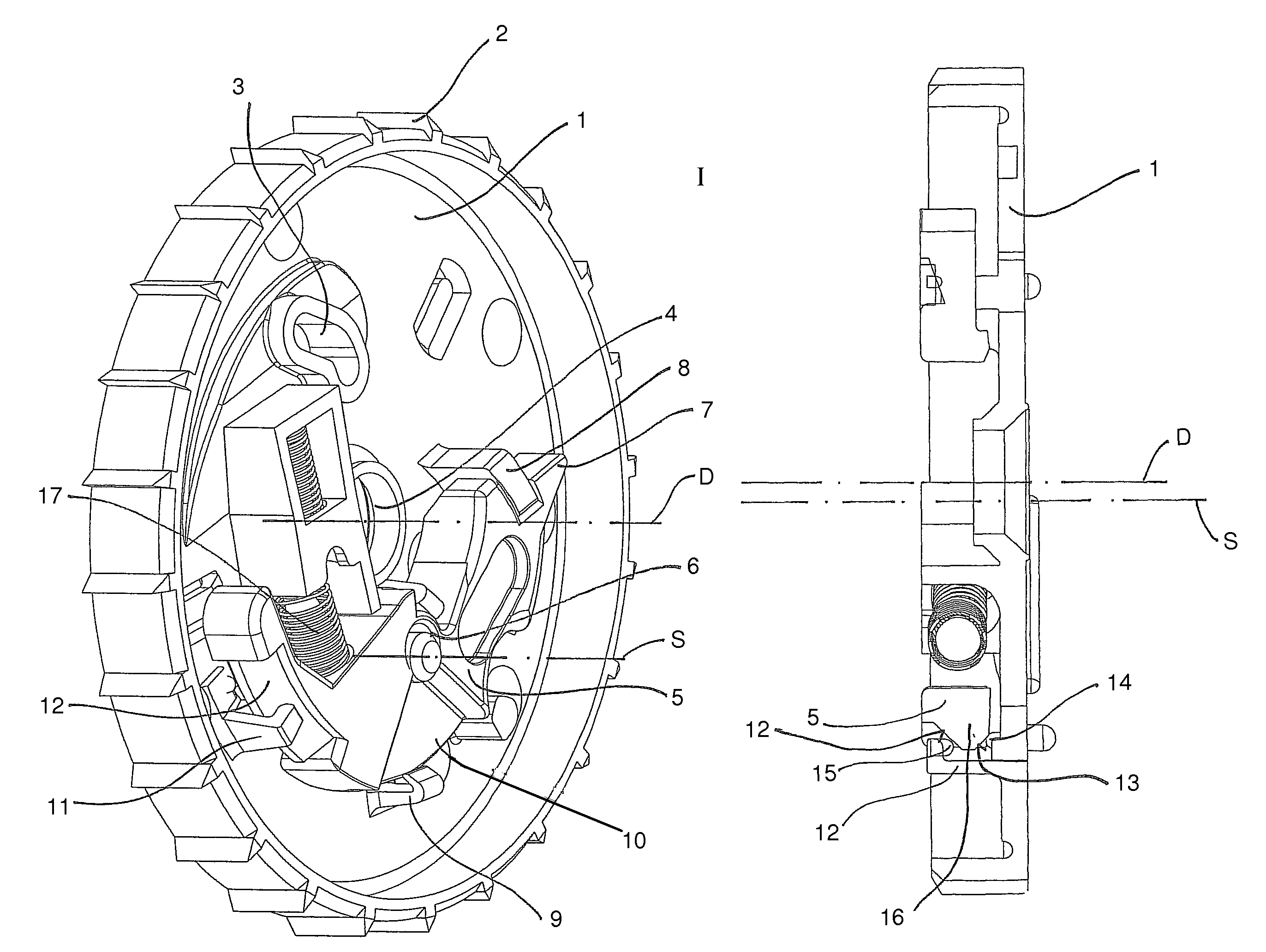
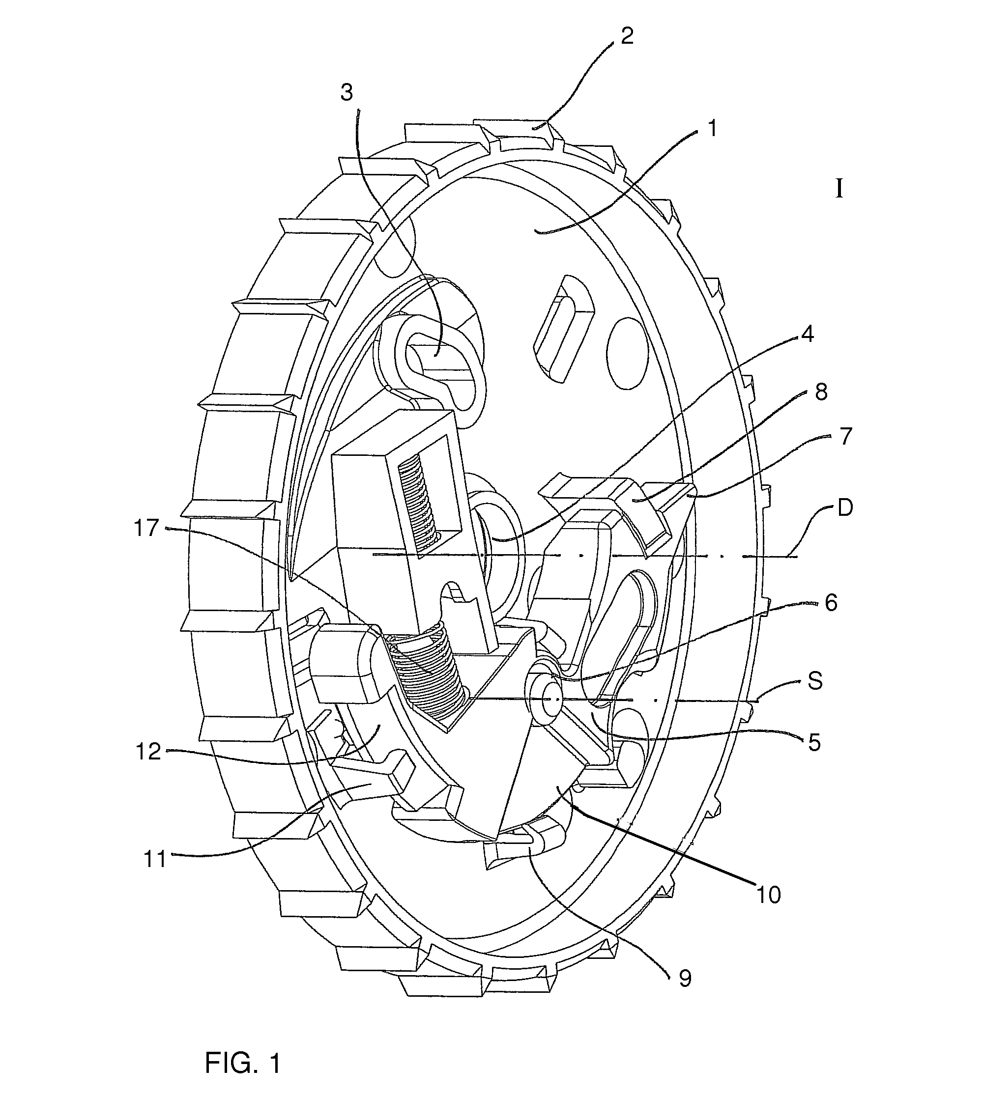
[0020]FIG. 1 presents a disc cam 1 which is rotatably mounted in a mount 4 and rotates around a rotation axis D on a belt shaft (not depicted) of a seat belt retractor and is spring-tensioned opposite it in the extension direction of a safety belt coiled on the belt shaft. A bean-shaped control recess 3 is provided on the disc cam 1 and the control pin of a blocking catch mounted on the belt shaft engages therein. The blocking catch forms a blocking device which guides into a gearing affixed to the belt retractor to block the belt shaft in the direction of extension of the safety belt. The control of the blocking catch is thereby affected by a stopping of the disc cam 1 with respect to the belt shaft, whereby the movement of the blocking catch is caused by the control pin engaging in the bean-shaped control recess 3. The belt shaft, the blocking catch, the frame, and other parts of the belt retractor are intentionally not depicted for a better overall comprehension. Since they are n...


PUM


Abstract

A self-locking belt retractor with a belt shaft which is mounted rotatably in a frame having a belt-sensitive a blocking device. A disc cam (1) mounted rotatably on the belt shaft, is pretensioned by a spring in the extension direction of the seat belt and on which an inertial mass (5) is mounted pivotably about a pivot axis (S). A projection (11) limits relative movement between the inertial mass (5) and the disc cam (1) is provided on the inertial mass (5) and / or on the disc cam (1).

Description

CROSS REFERENCE TO RELATED APPLICATIONS[0001]This application claims priority to German Patent Application No. 10 201 0 046 980.7, filed Sep. 30, 2010 and PCT / EP2011 / 004564, filed Sep. 10, 2011.FIELD OF THE INVENTION[0002]The invention relates to a self-locking seat belt retractor for a motor vehicle occupant restraint system.BACKGROUND OF THE INVENTION[0003]Self-locking seat belt retractors are generally used in safety belt devices of vehicles in order to roll up a non-emplaced safety belt in a park position and to enable a variable pull-out of the safety belt when it is deployed for restraining an occupant with as little slack as possible. For that purpose, a belt shaft mounted so as to rotate in the seat belt retractor and spring-tensioned in the roll-up (retraction) direction is provided on which the safety belt can be rolled up. In addition, the seat belt retractor may features a blocking (locking) mechanism which is activated when a predetermined extension acceleration of the ...

Claims


Application Information

Patent Timeline
Patent Type & Authority Patents(United States)
IPC IPC(8): B60R22/38B60R22/34
CPCB60R22/38B60R22/341
Inventor BOSSE, UWEHEINE, VOLKMARBUTENOP, KLAUS WERNER
Owner AUTOLIV DEV AB
Why Eureka
Try Eureka