Electrical conduit connector with two-point engagement

a technology of electrical conduit and connector body, which is applied in the direction of coupling, coupling device connection, transportation and packaging, etc., can solve the problems of devices taking space within the connector body, conduit or cable may not be held firmly in place, and the use of conduit or cable within the connector body often does not provide a good grasp

Active Publication Date: 2014-02-11
ATKORE STEEL COMPONENTS INC
View PDF8 Cites 29 Cited by
  • Summary
  • Abstract
  • Description
  • Claims
  • Application Information

AI Technical Summary

Benefits of technology

[0005]The body 12 includes a body outer surface 18 extending between a body first axial end 14 and a body second axial end 16. The internal passage 20 of the body 12, which has a central passage axis, extends between the body first axial end 14 and the body second axial end 16. A body first region 28 (adjacent to the body first axial end 14) includes a first slot 30 and a second slot 32, each of which may have an elongated shape. The body 12 may further include a body second region 42 (adjacent to the body second axial end 16) that has a threaded second region outer surface 44, allowing the body second region 42 to interface with other components (such as a junction box) having threaded or grooved surfaces. For example, the locknut 46 may interface with the body second region 42 through its threaded locknut inner surface 48. The body 12 may furthermore include a body middle region 50 with an outer surface that is irregular to enhance gripping. By gripping the body middle region 50, a user may more easily rotate the body 12 in order to thread the body second region 42 into various components.
[0012]The fastening clip 82 engages with the fastener body 80 to prevent the fastener body 80 from withdrawing from the clip fastener aperture 64 and maintaining the fastener 76 together with the connector clip 60. The fastening clip 82 is engaged to the fastener body 80 of the fastener 76 on the side of the clip body 62 opposite the fastener head 78. The fastening clip 82 fits into the threads of the outer surface of the fastener body 80, wrapping at least partially around the fastener body 80 (see FIG. 2). The fastening clip 82 may be shaped as an open wire loop with a circumferential gap 86 (labeled in FIG. 2) between a first circumferential end 88 and a second circumferential end 90. The fastening clip 82 preferably sandwiches clip body 62 against the fastener head 78, thereby helping to prevent the connector clip 60 from falling through the first and second slots 30 and 32 of the body 12 as the fastener 76 is withdrawn from the body aperture region 52. Because of the fastening clip 82, the connector clip 60 rises with the fastener 76 as the fastener 76 is withdrawn from the fastener aperture 58. As the connector clip 60 rises, the clip first tooth 66 and second tooth 68 withdraw from the internal passage 20. The fastening clip 82 thus keeps the user from having to hold onto the connector clip 60 while assembling and disassembling the connector assembly 10. For example, the user does not have to hold onto the connector clip 60 with one hand while inserting the cable 24 through the internal passage 20 with another hand.
[0013]The connector assembly 10 provides significant advantages, as further discussed below. For example, the orientation and shape of the first and second slots 30 and 32 permit the engaging ends 70 and 72 of the clip first tooth 66 and second tooth 68, respectively, to complementarily interfit with conduit grooves 74, effectively securing the conduit 22 to the body 12. The body aperture region 52 allows the fastener body 80 to extend into the internal passage 20 without obstructing the conduit 22 and cable 24. The aperture flange 54 provides more surface for engagement with the fastener body 80 as the fastener 76 enters the body fastener aperture 58. The fastening clip 82 makes the assembly, disassembly, and general use of the connector assembly 10 easier and more convenient. The connector assembly 10 may also be modified in various ways to make it highly versatile for various uses and settings, as discussed below.

Problems solved by technology

The devices used to hold the conduit or cable within the connector body often do not provide a good grasp, so the conduit or cable may not be held firmly in place.
Also, these devices may take space within the connector body, space that would otherwise be available for the conduit or cable inserted through the connector body.
The devices are additionally often not easy to use.

Method used


Image

  • Electrical conduit connector with two-point engagement
  • Electrical conduit connector with two-point engagement
  • Electrical conduit connector with two-point engagement

Examples


Embodiment Construction

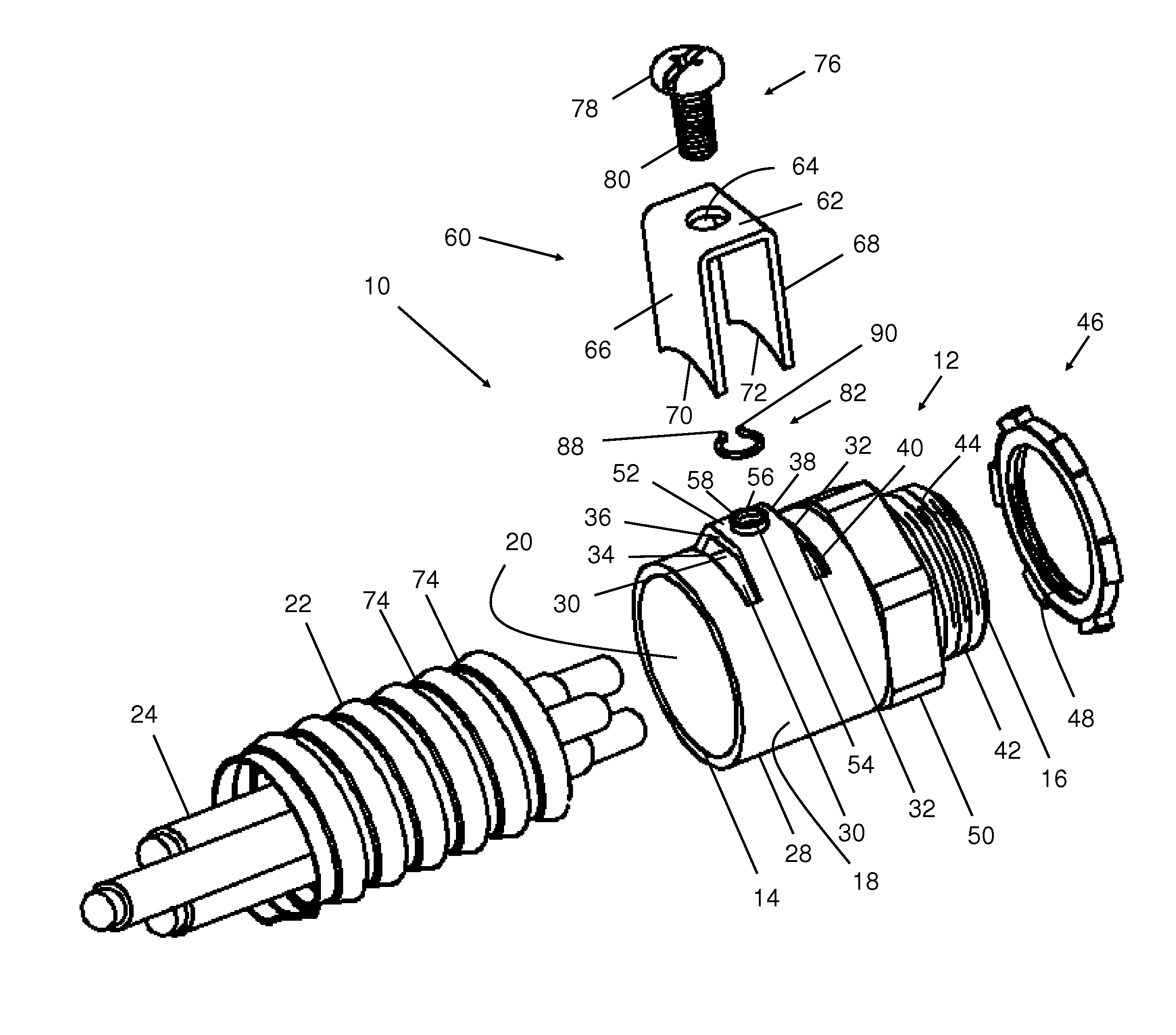
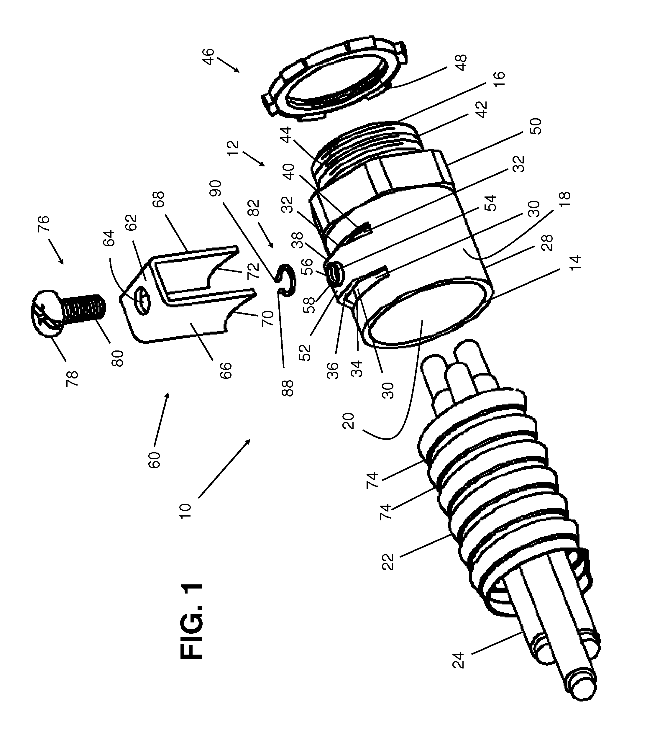
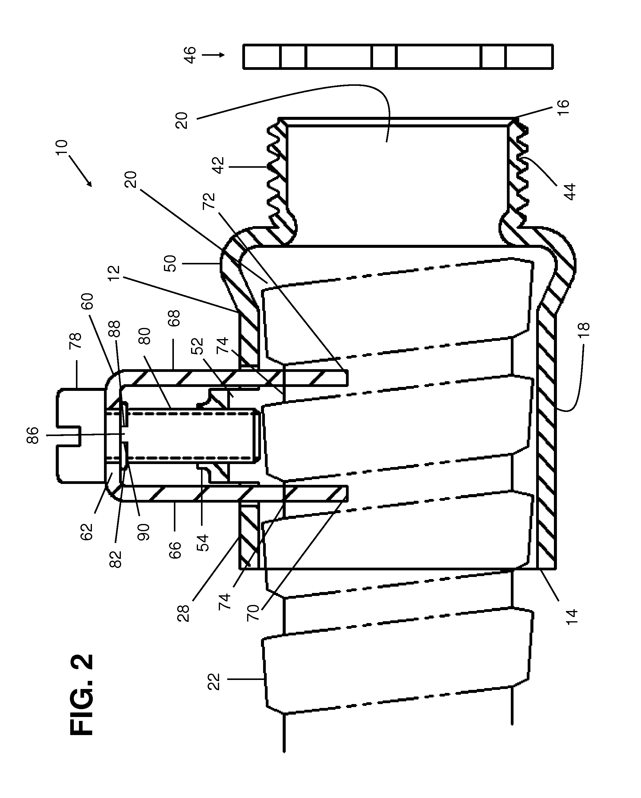
[0017]Continuing the discussion of the Summary section above, FIG. 2 depicts a cut-away side view of the exemplary connector assembly 10 of FIG. 1. The elongated body 12 is shown with the conduit 22 inserted through the internal passage 20. The inner diameter of the body first region 28 and the outer diameter of the conduit 22 are greater than the inner diameter of the body second region 42. This provides a barrier to the further insertion of the conduit 22 into the body second region 42, but allows the cable 24 within the conduit 22 to extend into the body second region 42 (not shown). Also, the diameters of the body first region 28, the body middle region 50, the body second region 42, and the conduit 22 can be adjusted as desired. Moreover, the diameters of the components need not be changed in stepwise fashion, and may increase or decrease gradually along the length of the body 12.

[0018]The conduit 22 is threaded, with conduit grooves 74 along its length, allowing the conduit 22...


PUM


Abstract

An exemplary connector assembly includes an elongated body with an internal passage for a conduit or cables. A body aperture region with a body fastener aperture is set between two elongated slots. The body aperture region may radially bulge out from the body, and may alternatively or additionally include an aperture flange protruding from the body aperture region. A U-shaped connector clip includes two parallel teeth that are inserted in the two slots, and a clip body having a clip fastener aperture. A fastener is inserted through the fastener apertures, securing the connector clip to the body. A fastening clip secures the fastener to the connector clip and keeps the connector clip from falling back into the slots as the connector clip is being disengaged from the body. Each clip tooth includes an engaging end that is complementarily interfittable with grooves in the conduit, keeping the conduit in place.

Description

FIELD OF THE INVENTION[0001]This document concerns an invention relating generally to connector assemblies that house conduits and cables, such as electrical cables.BACKGROUND OF THE INVENTION[0002]Connector assemblies can be used to bring conduits and cables (such as electrical cables) together in various configurations. A cylindrical connector body may have a cable inserted through a first end, and have a threaded second end which can be inserted into, and attached within, a junction box. A conduit or cable within the connector body, however, may need to be held in place so that it does not move through the connector body. The devices used to hold the conduit or cable within the connector body often do not provide a good grasp, so the conduit or cable may not be held firmly in place. Also, these devices may take space within the connector body, space that would otherwise be available for the conduit or cable inserted through the connector body. The devices are additionally often n...

Claims


Application Information

Patent Timeline
Patent Type & Authority Patents(United States)
IPC IPC(8): F16L19/00
CPCH02G3/06F16L25/08F16L25/0036H02G3/0691H02G3/0468F16L19/00
Inventor SHEMTOV, SAMI
Owner ATKORE STEEL COMPONENTS INC
Why Eureka
Try Eureka