Recording position error measurement apparatus and method, image forming apparatus and method, and computer-readable medium

a technology of recording position error and measurement apparatus, which is applied in the direction of digitally marking record carriers, instruments, visual presentation using printers, etc., can solve the problems of recording position error, streaky artifacts in recorded images on recording mediums, and image recording position errors, etc., to achieve accurate identification and excellent robustness

Inactive Publication Date: 2014-02-11
FUJIFILM CORP
View PDF7 Cites 16 Cited by
  • Summary
  • Abstract
  • Description
  • Claims
  • Application Information

AI Technical Summary

Benefits of technology

[0014]In light of these circumstances, the present invention has been derived for an object of providing a recording position error measurement apparatus and method whereby recording position errors of recording elements in a recording head can be measured accurately, even if using a reading apparatus having a resolution lower than the recording resolution. A further object of the present invention is to provide an image forming apparatus and method, and a program, which are based on this measurement method.
[0021]According to the present invention, a prediction signal is calculated from a read image signal obtained by reading a test pattern, and the regularity (periodicity) of the line-shaped pattern is used to ascertain the relationship between the signal change and the error (distance) between the recording position and this prediction signal. Then respective threshold values are specified for each measurement distance. By this means, it is possible accurately to identify the recording position errors of recording elements, from a read image signal having a lower resolution than the recording resolution of the recording head.
[0022]Moreover, since the threshold values for judgment are specified on the basis of the prediction signal which is calculated from the read image signal, it is possible to achieve high-precision measurement having excellent robustness, which means that a measurement is not affected by the characteristics of the reading apparatus, the recording conditions of the test pattern, or the like.

Problems solved by technology

However, with a full-line head image rendering apparatus, a deviation of an actual dot position that is recorded on a recording medium from an ideal dot position due to various reasons such as production variation, deterioration with age, or the like of recording elements (nozzles) constituting an ejecting unit may cause a recording position error (deposited position error).
As a result, a problem that streaky artifacts occur in an image recorded on the recording medium arises.
In addition to artifacts due to such a recording position error, there are phenomena in which streaky artifacts occur in a recorded image on the recording medium due to failures in a recording element such as an abnormality in which droplets are not ejected (non-ejection), an abnormality in volume of ejected droplets, and an abnormality in shape of ejected droplets (splash).
In such a large number of recording elements, defective ejection nozzles may occur at various timings.
More specifically, a nozzle may become defective at the time of manufacture of a recording head, a nozzle may become defective due to deterioration with age, a nozzle may become defective during maintenance (in case of maintenance-induced, the nozzle is often restored to a normal nozzle by a next maintenance), and a recording element may become a defective ejection nozzle midway through continuous printing.
However, Japanese Patent Application Publication No. 2004-009474 and Japanese Patent Application Publication No. 2006-069027 do not disclose detection technology which addresses the issue of using a reading apparatus having a lower resolution than the print resolution of the line head.
However, in the technology disclosed in Japanese Patent Application Publication No. 2007-054970, under conditions where the line width formed by dots on a test pattern does not satisfy the sampling theorem, the line position retains a certain amount of error (estimated error in the line profile formed by the dots), and thus there is a possibility that accuracy of the detection cannot be achieved to the high point.

Method used


Image

  • Recording position error measurement apparatus and method, image forming apparatus and method, and computer-readable medium
  • Recording position error measurement apparatus and method, image forming apparatus and method, and computer-readable medium
  • Recording position error measurement apparatus and method, image forming apparatus and method, and computer-readable medium

Examples


example 1

[0298]On the basis of the depositing position (distance) information, nozzles having a certain distance or greater are set as defective, whereupon it is judged whether or not there is a concentration of defective nozzles, and if there is a concentration corresponding to prescribed conditions or greater, then a nozzle satisfying a predetermined condition, of these nozzles (for example, the nozzle having the smallest depositing position error) is changed so as to be treated as a normal nozzle rather than a defective nozzle.

[0299]Beneficial effects of processing of this kind are as follows. More specifically, if there is a certain concentration or more of defective nozzles and all of the nozzles are treated as defective (set as non-ejecting nozzles), then the resulting blank gap becomes more prominent. To give a simple example, it is supposed that three consecutive nozzles are judged to be defective nozzles. In a case of this kind, of the plurality of nozzles judged to be defective, th...

example 2

[0300]The distance between the depositing positions of nozzles is calculated from the depositing position error (including the plus and minus signs), and a pair of nozzles having a distance between the respective depositing positions that does not satisfy a prescribed condition is extracted and the nozzle thereof having the larger depositing position error is judged to be defective.

Description of Print Layout

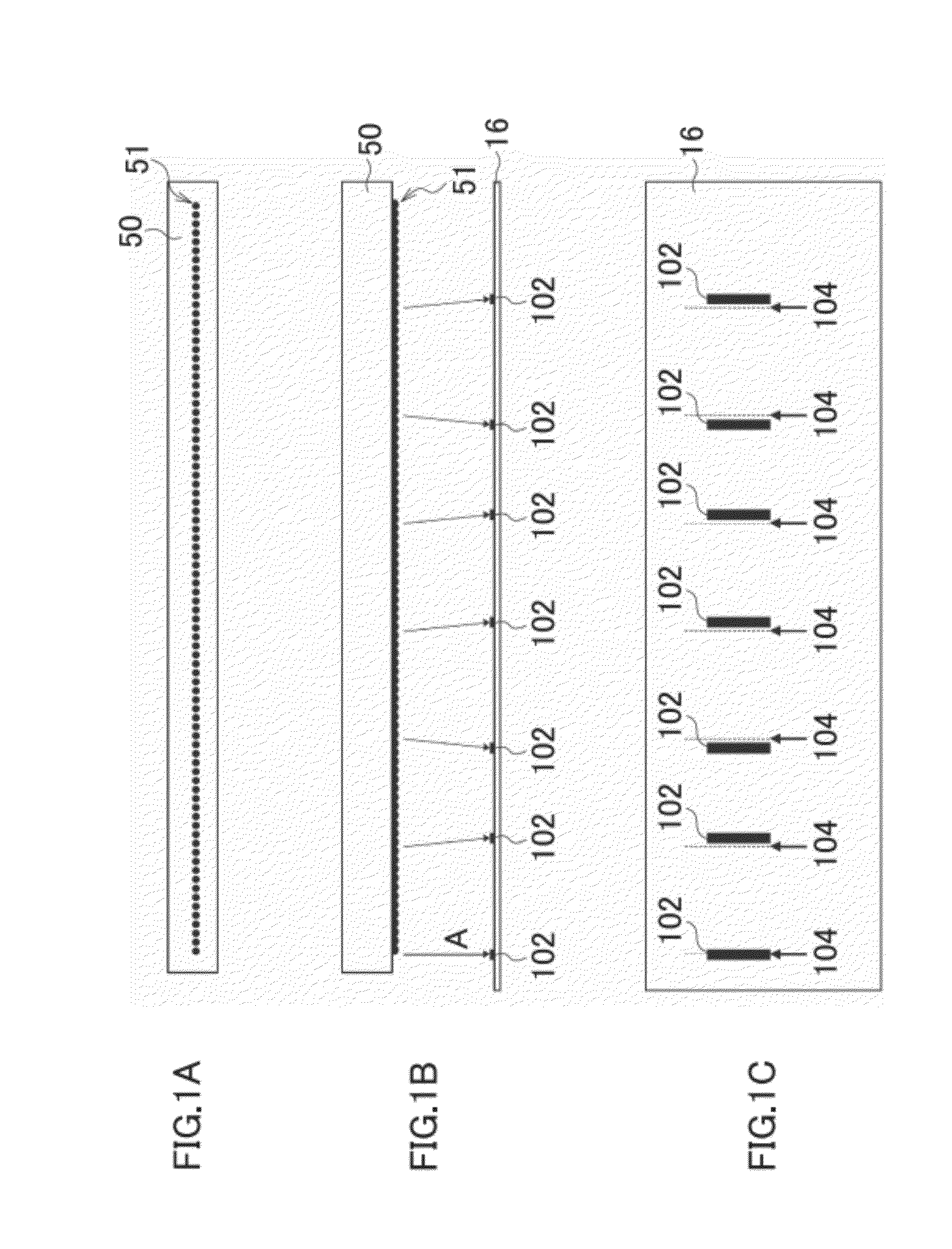
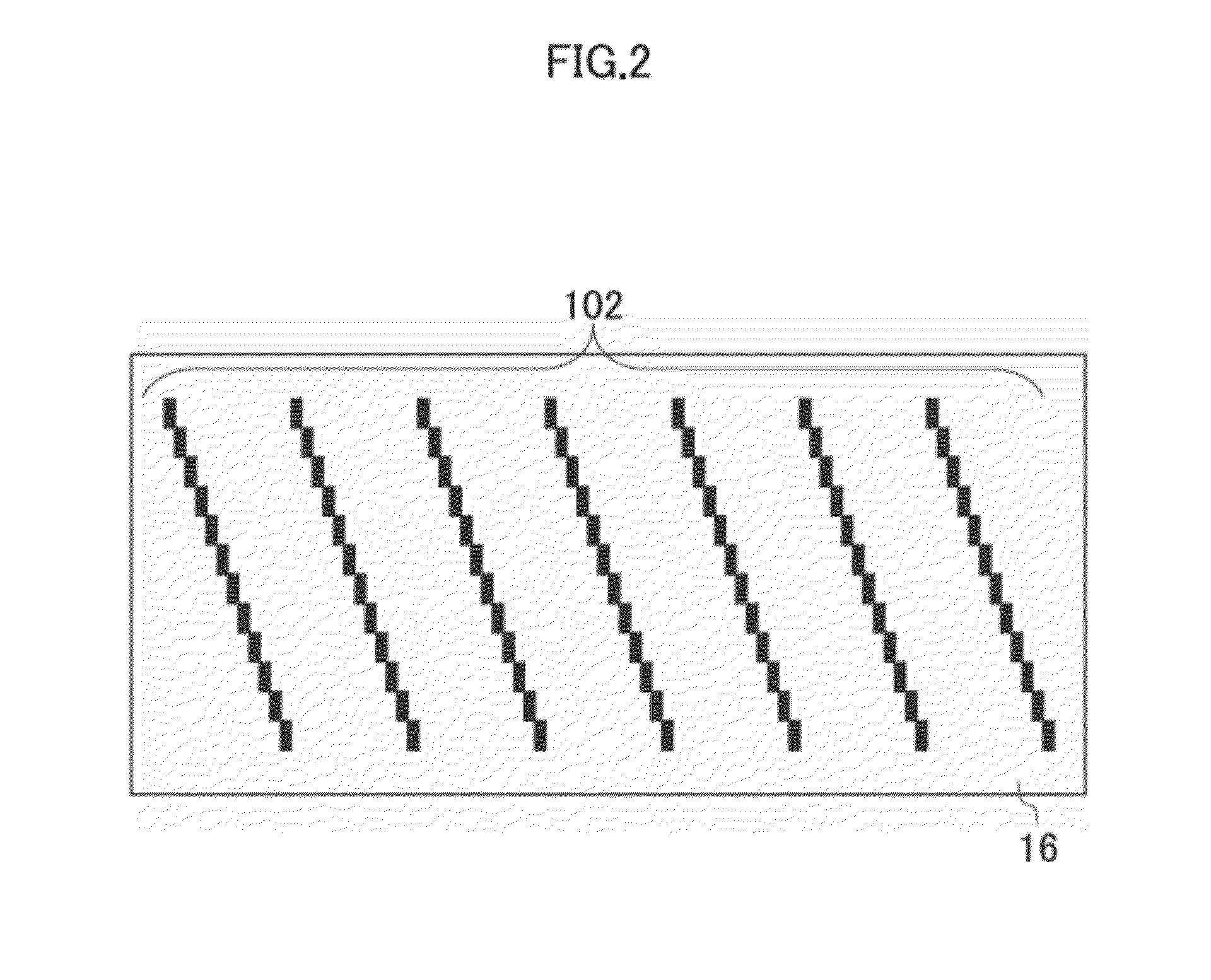
[0301]Next, an example of the print layout on the recording paper 16 will be described. FIG. 49 is a diagram showing the layout on the printing paper of a system for detecting and correcting defective ejection nozzles. The upper side in FIG. 49 is the leading end of the recording paper 16, and the recording paper 16 is conveyed from bottom to top in FIG. 49 (in the conveyance direction indicated by the arrow C). For instance, in the case of a drum conveyance method where recording paper 16 is fixed onto the circumferential surface of a drum (not illustrated) and the recording pa...


PUM


Abstract

A recording position error measurement apparatus includes a read image signal acquisition device and a signal processing device having: a dividing device which divides pixel series of the read image signal into sequences having different remainder values so as to generate image signals of the respective sequences; a prediction signal generation device which calculates regular prediction signals which are predicted with respect to the respective sequences, according to the read image signal; a threshold value determination device which determines tone value differences corresponding to respective distances representing recording position errors from the prediction signals, and which determines threshold values corresponding respectively to the recording position errors, from the tone value differences; a change signal calculation device which calculates a change signal indicating a difference between the prediction signal and the image signal of each of the sequences; and an error distance calculation device which specifies the recording position errors of the plurality of recording elements in the recording head according to comparing the change signal with each of the threshold values.

Description

BACKGROUND OF THE INVENTION[0001]1. Field of the Invention[0002]The present invention relates to a detecting technique for measuring recording position error from a test pattern recording result recorded with a recording head (for example, an inkjet head) having a plurality of recording elements, and an image forming technique to which the detecting technique is applied.[0003]2. Description of the Related Art[0004]Methods of recording an image on a recording medium such as a recording paper include an inkjet drawing system in which ink drops are ejected from a recording head in accordance with an image signal and the ink drops are deposited on the recording medium. An example of an image drawing apparatus using such an inkjet drawing system is a full-line head image rendering apparatus in which an ejecting unit (a plurality of nozzles) that ejects ink drops is linearly disposed to correspond to an entire area of one side of a recording medium, and the recording medium is conveyed in...

Claims


Application Information

Patent Timeline
Patent Type & Authority Patents(United States)
IPC IPC(8): B41J29/393
CPCB41J2/2135B41J2/2146H04N2201/04717B41J2/2142
Inventor YAMAZAKI, YOSHIROU
Owner FUJIFILM CORP
Why Eureka
Try Eureka