Constrained folded path resonant white light scintillator

a scintillator and folded path technology, applied in the direction of discharge tube luminescnet screens, semiconductor devices of light sources, lighting and heating apparatus, etc., can solve the problems of increasing manufacturing costs, hurdling impeding the realization of energy savings, and increasing installation or manufacturing costs, so as to improve utilization and containment of pump light, the effect of reducing the conversion and emission of white ligh

Active Publication Date: 2014-02-11
VENTURA MFG1 LLC
View PDF60 Cites 16 Cited by
  • Summary
  • Abstract
  • Description
  • Claims
  • Application Information

AI Technical Summary

Benefits of technology

[0009]The volumetric light emitter can be optically bonded to one or more emitter junctions as a final step, thus creating a simple volumetric light engine wherever a light filament or arc may be used. This invention acts as a bridging technology between LED junction manufacturers and luminaire manufacturers, which delivers the lighting requirements to the end user. This allows for a common design to be implemented with a variety of LED junctions and heat sink arrangements. Another benefit of this invention lies in integrating three specific optical tasks into one simple and manufacturable form. The three optical tasks are: 1) light gathering and placement from emitter junctions, 2) improving utilization and containment of pump light, and 3) down conversion and emission of white light. This integration opens up new designs for luminaires and possesses the benefit of ease of retrofitting older structures with LED sources.

Problems solved by technology

A major hurdle impeding the realization of energy savings, however, is the cost of installation or manufacturing.
In particular, many of the new technological improvements which greatly improve the luminous efficacy of white LEDs come with disadvantages in the manufacturing process.
This is a straightforward process and as such any improvements to increase the luminosity output add complications to this process which can increase the manufacturing cost.
Failures that plague the above approach include heat degradation of the phosphor due to its proximity to the emitter junctions.
The encapsulant degrades with higher temperatures, often resulting in discoloration and inefficient transmitters in the blue or the visible wavelength region.
Additionally, the encapsulant acts as a thermal blanket on top of the emitter junctions causing a further loss of efficiency.
There exists another limitation to the above approach: the relatively small area of emission.
Such brightness levels can pose a threat to the human vision system and can contribute to migraines, seizures, and temporary washout of the human eye.
Yet another limitation to the above approach is that it is not directly scalable.
It is not an easy task to increase luminosity by adding more emitter junctions and thicker layers of phosphor.

Method used


Image

  • Constrained folded path resonant white light scintillator
  • Constrained folded path resonant white light scintillator
  • Constrained folded path resonant white light scintillator

Examples


first embodiment

I. First Embodiment

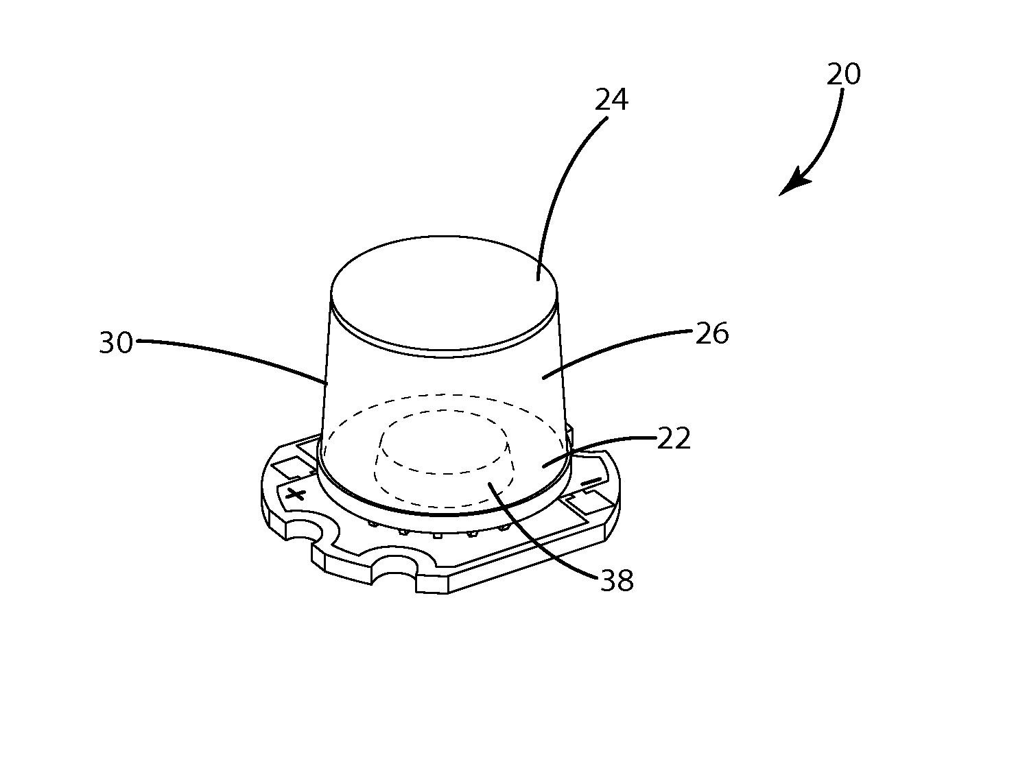
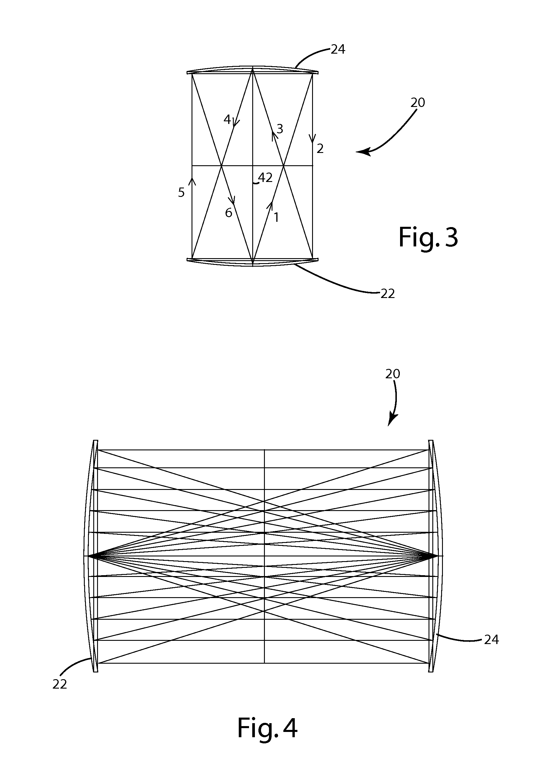
[0035]A volumetric white light emitter in accordance with an embodiment of the present invention is illustrated in FIGS. 1-8 and generally designated 20. The volumetric white light emitter 20 includes a first conic reflector 22, a second conic reflector 24, and a volumetric light conversion element 26 extending between the first conic reflector 22 and the second conic reflector 24. The first conic reflector 22 defines an aperture 28 for a light source or emitter junction (not shown), and the second conic reflector 24 is orientated opposite the first conic reflector for reflecting light from the light source toward the first reflector 22. A convex mirror 32 is positioned adjacent the vertex 34 of the second conic reflector 24. The second conic reflector 24 is shown as parabolic with a focus at the aperture 28 of the first conic reflector 22. Additionally, an elliptical element 38 is positioned adjacent the first conic reflector 22. The elliptical element 38 defines...

second embodiment

II. Second Embodiment

[0041]A folded spherical cavity 50 in accordance with another embodiment of the present invention is shown in FIG. 9. The folded spherical cavity 50 includes a spherical reflector 52, a planar reflector 54 opposite the spherical reflector 52, and a volumetric light conversion element 56 extending between the spherical reflector 52 and the planar reflector 54. The spherical reflector 52 defines an aperture or seat (not shown) for a light source or emitter junction. Though not shown, a convex mirror can be positioned adjacent the planar reflector 54. Additionally, an elliptical element (not shown) can be positioned adjacent the spherical reflector 52. The elliptical element can also include an aperture coincident with the spherical reflector aperture to direct light from the light source toward the planar reflector 54. The volumetric light conversion element 56 includes phosphor particles dispersed in a resin to convert light emitted by the light source from a fir...

third embodiment

III. Third Embodiment

[0042]A folded transverse cavity 70 in accordance with an embodiment of the present invention is shown in FIG. 10. The folded transverse cavity 70 includes a frusto-conical reflector 72, a conic reflector 74 opposite the frusto-conical reflector 72, and a volumetric light conversion element 76 extending between at least a portion of the frusto-conical reflector 72 and at least a portion of the conic reflector 74. The frusto-conical reflector 72 defines an aperture or seat (not shown) for a light source or emitter junction (not shown). The conic reflector 74 is orientated opposite the frusto-conical reflector 72 for reflecting light from the light source toward the frusto-conical reflector 72. A convex mirror 78 is positioned adjacent the vertex 80 of the conic reflector 74. The conic reflector 74 is shown as parabolic with a focus at the aperture of the frusto-conical reflector 72. Though not shown, an elliptical element can be positioned adjacent the frusto-con...


PUM


Abstract

An optical emitter enabling conversion of light from a light source. The optical emitter includes a first conic reflector defining an aperture for receiving the light source, a second conic reflector opposite the first conic reflector for collimating light emitted by the light source, and a volumetric light conversion element between at least a portion of the first reflector and at least a portion of the second reflector. The optical emitter can also include a convex mirror adjacent the vertex of the second conic reflector, and an elliptical element adjacent the first conic reflector. The light conversion element can include phosphor dispersed in a resin to convert light from a first wavelength to light of a second, longer, wavelength, wherein converted light is emitted from the light conversion element.

Description

FIELD OF THE INVENTION[0001]This invention relates to light sources and the manufacturing of light sources. In particular, this invention relates to light sources and “light engines” that are used for specific light tasks including, for example, flash lights, automotive lights, streets and public areas as well as industrial area lighting and medical illumination.BACKGROUND OF THE INVENTION[0002]With the development of the Light Emitting Diode (LED) for use in the lighting industry, the opportunity for energy savings continues to be significant for individuals and society as a whole. A major hurdle impeding the realization of energy savings, however, is the cost of installation or manufacturing. In particular, many of the new technological improvements which greatly improve the luminous efficacy of white LEDs come with disadvantages in the manufacturing process.[0003]In the manufacturing of a common white light LED, a phosphor powder blend is normally mixed with an encapsulant and de...

Claims


Application Information

Patent Timeline
Patent Type & Authority Patents(United States)
IPC IPC(8): F21V7/09
CPCF21K9/00F21V13/08F21K9/50F21V7/0033H01L33/50H01L33/58F21K9/60
Inventor BRUNT, JR., HAROLD W.BOURGET, PAUL L.
Owner VENTURA MFG1 LLC
Why Eureka
Try Eureka