Hemodialysis or hemo(dia)filtration apparatus and a method for controlling a hemodialysis or hemo(dia)filtration apparatus

a technology of hemodialysis or hemo(dia)filtration apparatus and filtration apparatus, which is applied in the direction of haemofiltration, suction device, other medical devices, etc., can solve the problems of excessive and undesired increase of blood pressure in the circuit, and achieve high hemoconcentration, reduce risks, and construction simple and economical

Active Publication Date: 2014-02-11
GAMBRO LUNDIA AB
View PDF27 Cites 23 Cited by
  • Summary
  • Abstract
  • Description
  • Claims
  • Application Information

AI Technical Summary

Benefits of technology

[0014]An advantage of the invention is to provide a hemo(dia)filtration system and a relative control method which reduce the risks due to an undesired situation as a consequence of a high hemoconcentration in at least a tract of the extracorporeal circuit, in particular in the tract comprised between the ultrafiltration zone and the dilution zone located downstream of the above-mentioned ultrafiltration zone.
[0015]A further advantage is to make available a hemo(dia)filtration system and a relative control method which enable passage from a therapy with post-dilution (and / or pre / dilution) of the replacement fluid to a therapy without post-dilution (and / or pre / dilution), without generating undesired phenomena in the transition period, such as for example excessive hemoconcentration in a tract of the blood circuit, excessive increase of pressure in the venous branch of the blood circuit, the setting-off of alarms for exceeding the maximum safety threshold of the venous pressure, the blocking of the therapy due to the setting-off of an alarm, and so on.
[0016]A still further advantage is that the invention provides a hemodialysis or hemo(dia)filtration system which is constructionally simple and economical and, further, provides a safe and reliable control method for the system.
[0017]These aims and more besides are all attained by the present invention, as it is characterised in one or more of the appended claims.
[0018]Further characteristics and advantages of the present invention will better emerge from the detailed description that follows, of at least a preferred embodiment, illustrated by way of non-limiting example in the accompanying figures of the drawings.

Problems solved by technology

This leads to the risk of an excessive and undesired increase of the blood pressure in the circuit.

Method used


Image

  • Hemodialysis or hemo(dia)filtration apparatus and a method for controlling a hemodialysis or hemo(dia)filtration apparatus
  • Hemodialysis or hemo(dia)filtration apparatus and a method for controlling a hemodialysis or hemo(dia)filtration apparatus
  • Hemodialysis or hemo(dia)filtration apparatus and a method for controlling a hemodialysis or hemo(dia)filtration apparatus

Examples


Embodiment Construction

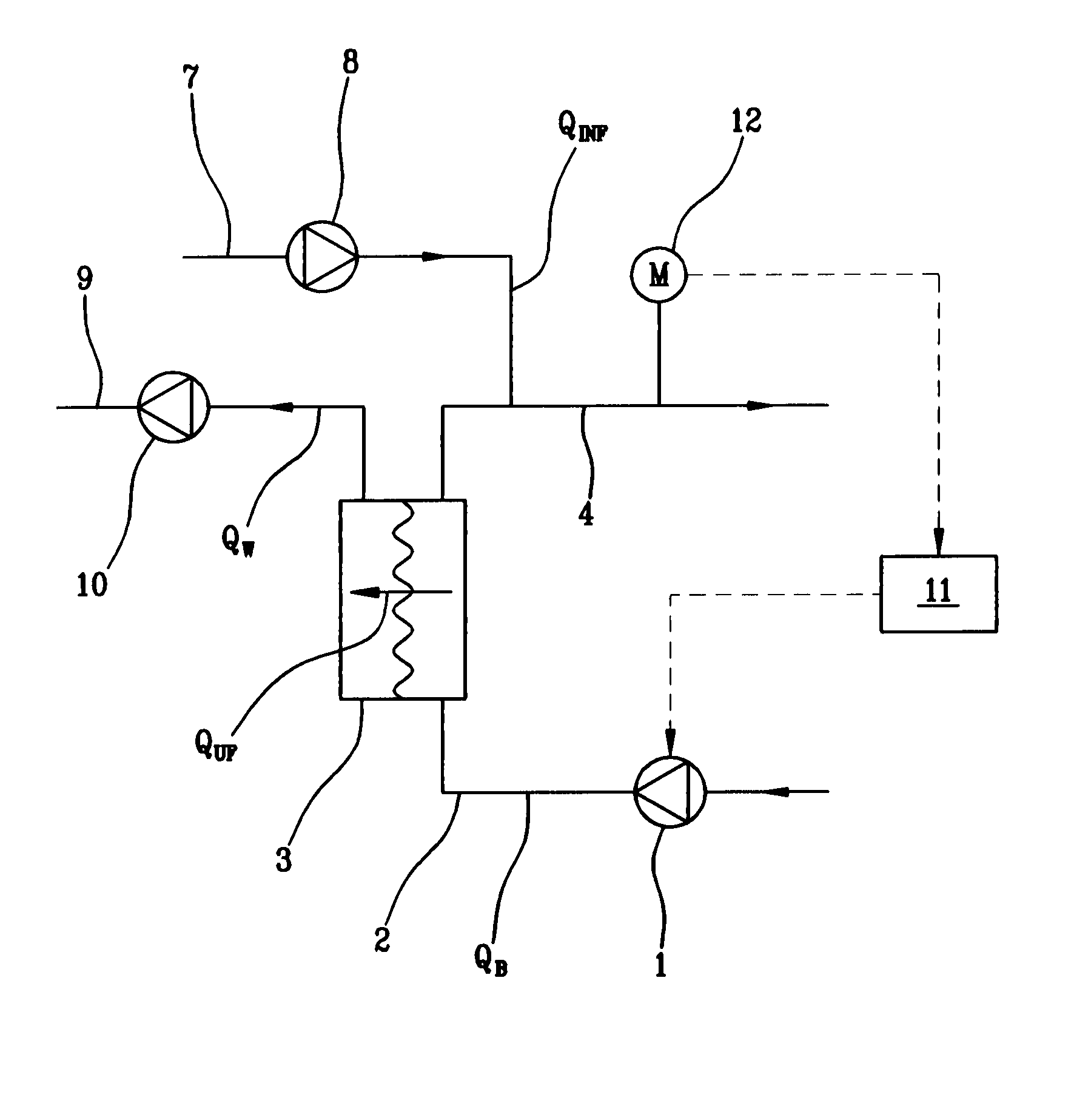
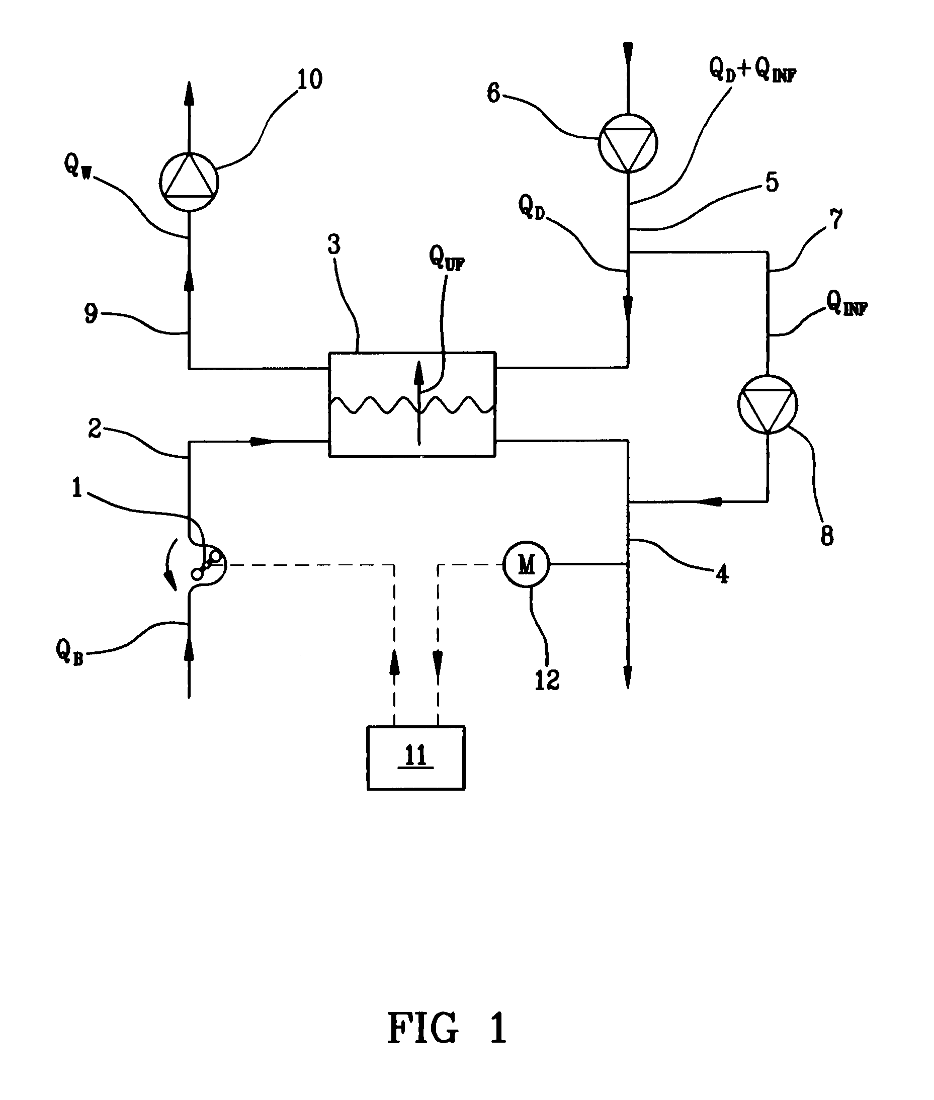
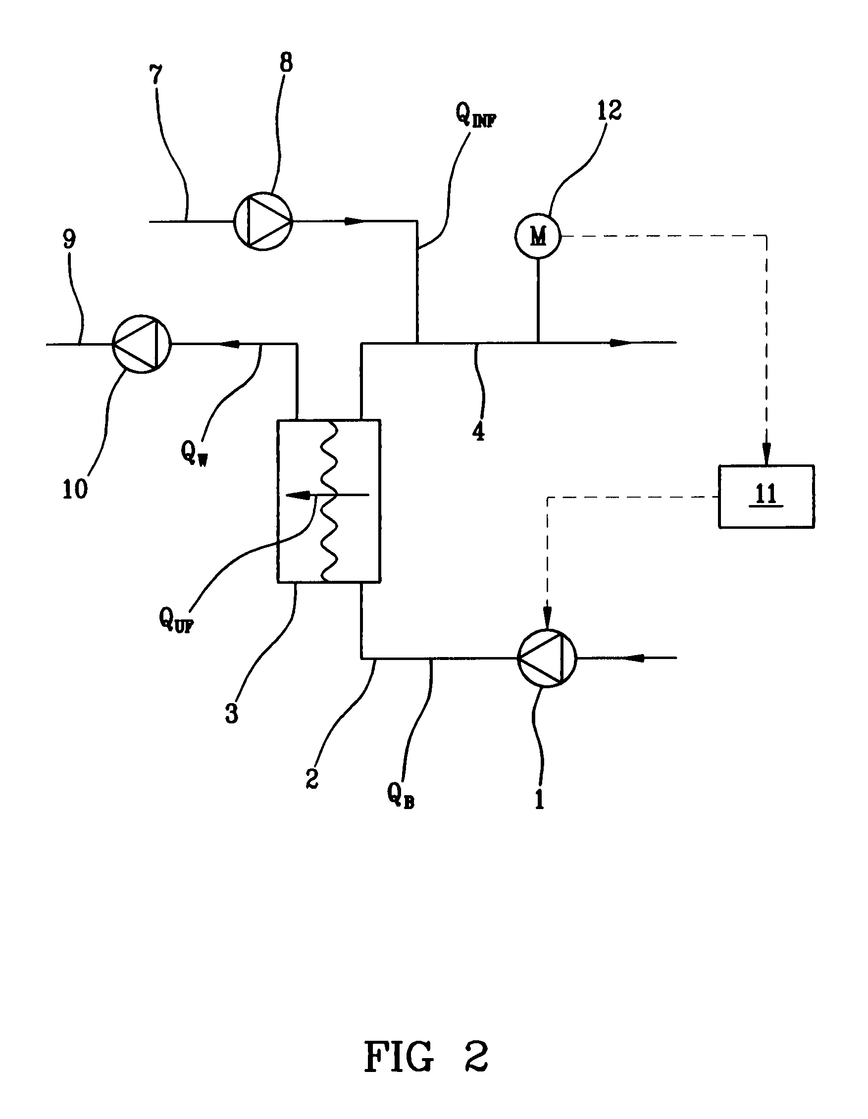
[0023]With reference to FIG. 1, 1 denotes a blood pump, 2 an arterial line, 3 a hemodiafilter, 4 a venous line, 5 a dialysis fluid supply line, 6 a dialysis fluid supply pump, 7 a replacement fluid supply line, 8 a replacement fluid pump, 9 a used fluid discharge line, 10 a used fluid drainage pump, 11 a control unit and 12 a venous pressure sensor.

[0024]The blood pump 1 can comprise any blood pump of known type. The blood pump 1 can be, as in the illustrated example, a flexible-wall deformation pump, for example a peristaltic pump, optionally a rotary pump. The blood pump 1 can comprise, for example, a volumetric pump, a positive-displacement pump, a membrane pump, a piston pump or any other actuator of known type, usable for extracorporeal blood transport. The blood pump 1 can be arranged, as in the illustrated example, along the arterial line 2 or along the venous line 4. It is possible to use a pump on the arterial line and a further pump on the venous line.

[0025]The arterial li...


PUM


Abstract

In a hemodiafiltration apparatus, a control and command unit (11) halts a replacement fluid supply pump (8) and contemporaneously modifies the control mode of a blood pump (1) passing from a control based on the pump velocity to a control based on the blood pressure measured by a sensor (12) arranged downstream of a hemodiafilter (3). The aim is to prevent risks due to excessive hemoconcentration in the blood circuit between the ultrafiltration zone and the infusion zone.

Description

BACKGROUND OF THE INVENTION[0001]The invention relates to a hemodialysis or hemo(dia)filtration apparatus and a method for controlling the apparatus.[0002]Specifically, though not exclusively, the invention can be usefully employed in any hemodialysis or hemo(dia)filtration apparatus of known type, for example for chronic therapy and / or intensive therapy.[0003]Reference is made in particular to a hemo(dia)filtration at least in post-dilution, i.e. with replacement fluid infusion at least downstream of the semipermeable membrane treatment device (hemo(dia)filter). The present invention can also be applied in hemo(dia)filtration combined with pre- and post-dilution, and in hemo(dia)filtration in mid-dilution, i.e. with replacement fluid infusion between two semipermeable membrane treatment devices arranged consecutively.[0004]As is known, in hemo(dia)filtration a part of the impure plasmatic liquid making up the extracorporeal blood is ultrafiltered through a semipermeable membrane an...

Claims


Application Information

Patent Timeline
Patent Type & Authority Patents(United States)
IPC IPC(8): A61M1/34A61M1/16A61M1/14A61M5/142
CPCA61M2205/3331A61M2001/3437A61M2001/3431A61M1/342A61M1/3639A61M1/3431A61M1/3437A61M1/3441A61M1/3434A61M1/16B01D61/32B01D61/22
Inventor MASALA, PIETROSUFFRITTI, MAUROWALLENBORG, ANDERSGEBHART, THOMAS
Owner GAMBRO LUNDIA AB
Why Eureka
Try Eureka