Seal

a technology of sealing and sealing plate, applied in the field of sealing plate, can solve the problems of increased friction and heat generation at the seal interface, increased energy consumption, and increased energy loss, and achieve the effect of improving sealing performance and facilitating mounting of inventive seals

Inactive Publication Date: 2014-02-18
AB SKF
View PDF24 Cites 4 Cited by
  • Summary
  • Abstract
  • Description
  • Claims
  • Application Information

AI Technical Summary

Benefits of technology

[0011]The sleeve-like section may be made of a stiff material so that in the unmounted condition, it retains its sleeve-like shape and remains substantially parallel to an axial centerline of the seal. A stiff sleeve is advantageous, as it enables optimal positioning of the sleeve relative to the component to be sealed, while the precise relative dimensioning allows optimal sealing performance. During rotational conditions, any rotational eccentricities are accommodated by the resilient section, which acts like a hinge. It does not exert a preloaded force on the sleeve-like section, and friction is therefore minimized. The resilient section must be able to withstand the friction torque generated at the sealing interface, as well as potential pressure differentials between an axially inner and axially outer side of the seal. If the sleeve-like section is mounted with a slight interference fit, the torque at start-up may be relatively high.
[0014]When executed in rubber or plastic, the inner diameter of the sleeve-like section relative to the outer diameter of the rotatable component may be selected to have a value smaller than one in the specified range. The advantage of a slight interference fit is that the sleeve-like section provides static sealing. When executed in metal, the inner diameter of the sleeve-like section relative the outer diameter of the rotatable component is preferably selected to have a value bigger than one in the specified range, so that it may be mounted with a slight clearance fit. A metal sleeve-like section has the advantage of greater wear resistance, thermal resistance and chemical resistance.
[0017]According to a further aspect of the invention, sealing performance may be enhanced by providing the sealing surface of the sleeve-like portion with hydrodynamic means. These may take the form of one or more sets of helical protrusions (for example ribs) or helical recesses (for example a spiral thread). The helical protrusions or recesses may be unidirectional, meaning that the helices are oriented with respect to the rotational direction of the rotatable component such that during rotation, a pumping action is realized which pumps the fluid to be retained towards the fluid-side of the seal. If the rotatable component is bidirectional, the sealing surface of the sleeve-like section may be provided with bidirectional helical recesses or helical protrusions, to enable pumping of the fluid in the desired direction, regardless of the rotational direction of the e.g. shaft.
[0019]In addition to the sealing surface, one or both end faces of the sleeve-like section may be provided with hydrodynamic means. For example, an end face could be provided with a sinusoidal surface geometry or with ramps in the form of a saw-tooth pattern, to direct the fluid to the fluid side of the seal. At the fluid side, the end face could also be executed with a lead-in chamfer, to facilitate mounting of the inventive seal.
[0022]A seal according to the invention comprises a stiff, sleeve-like sealing element which, in mounted condition, has extremely little play relative to the rotatable component. This minimizes friction during rotational conditions. The inventive seal also provides excellent dynamic and static sealing performance. Other advantages of the invention will become apparent from the detailed description and accompanying figures.

Problems solved by technology

In other words, the sealing element has a certain preload to keep it pressed against the rotating component and this leads to additional friction and heat generation at the seal interface.
The higher preload, however, increases the friction, which leads to a higher energy consumption and greater energy losses.

Method used


Image

  • Seal
  • Seal
  • Seal

Examples


Embodiment Construction

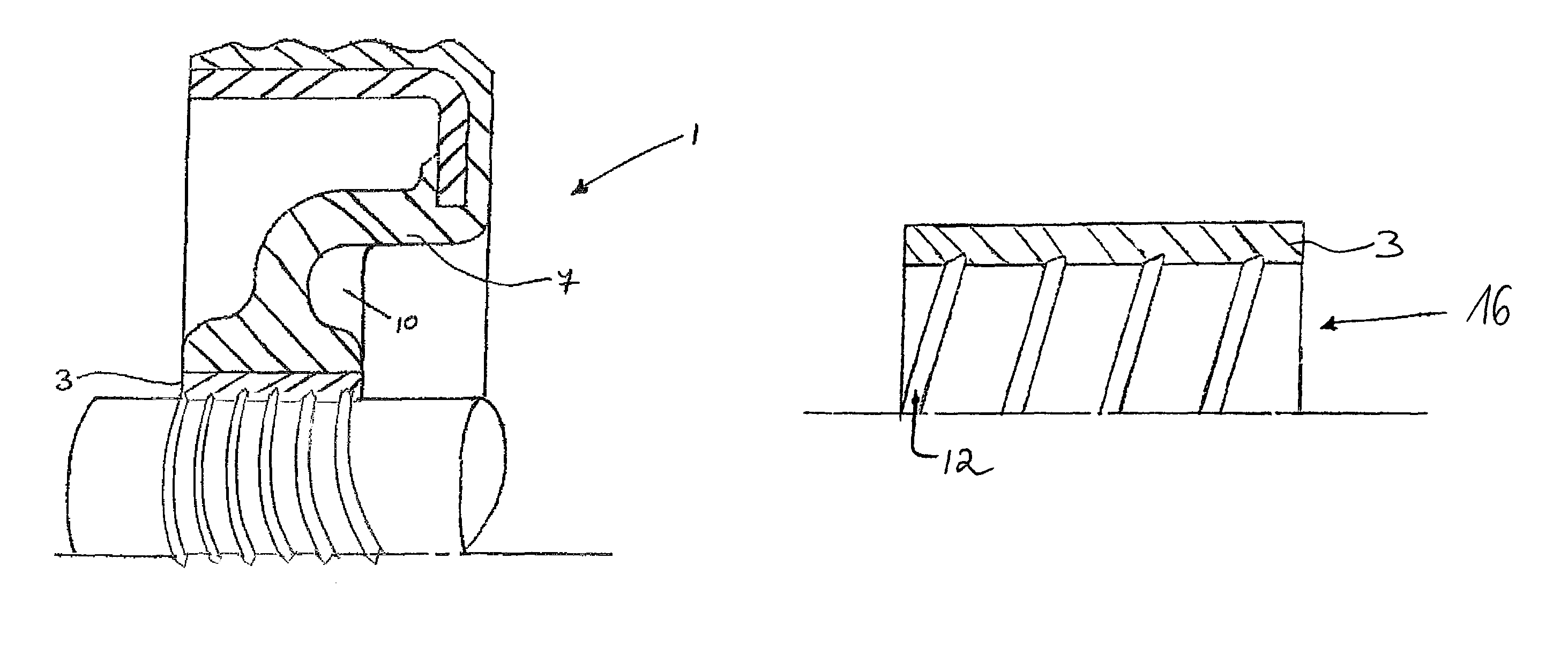
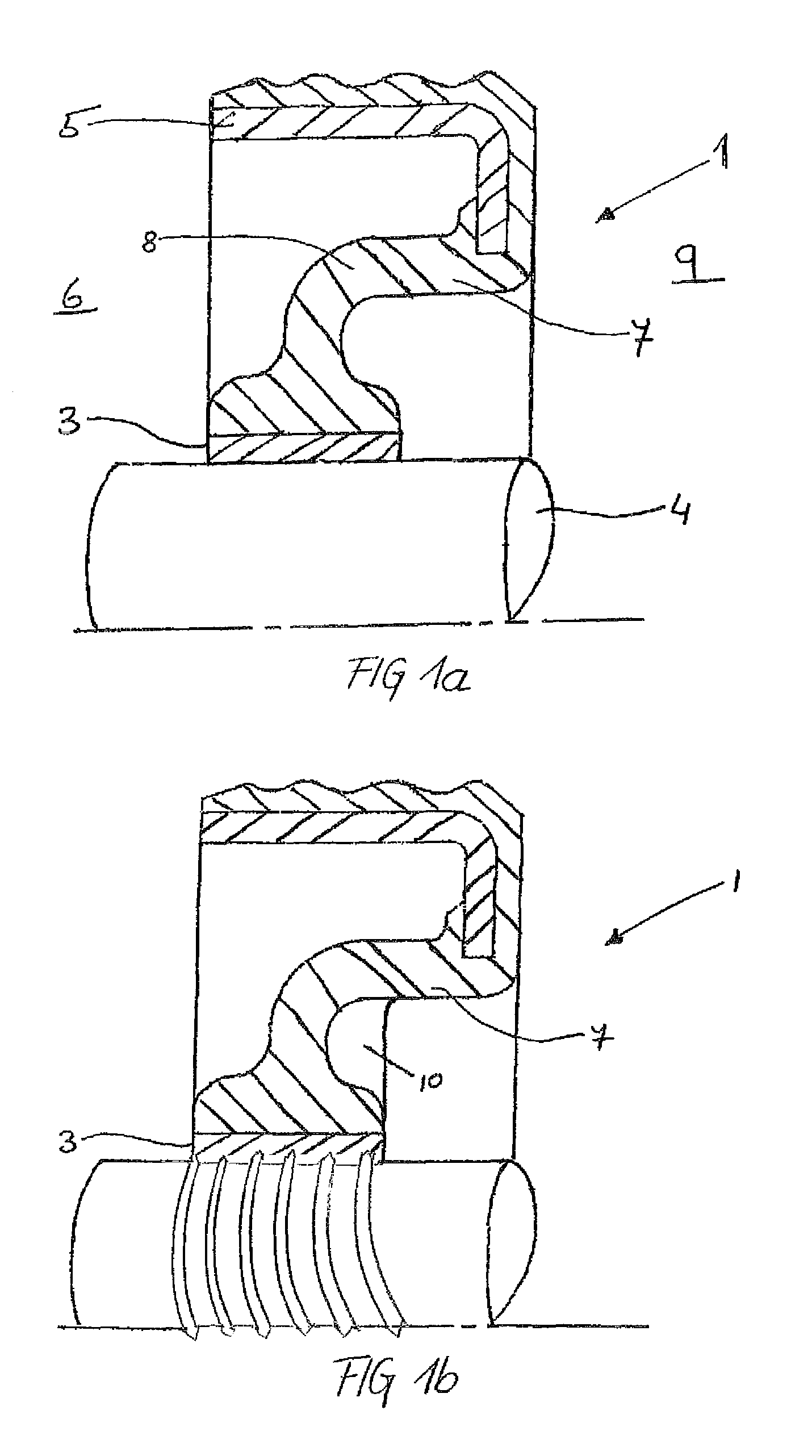
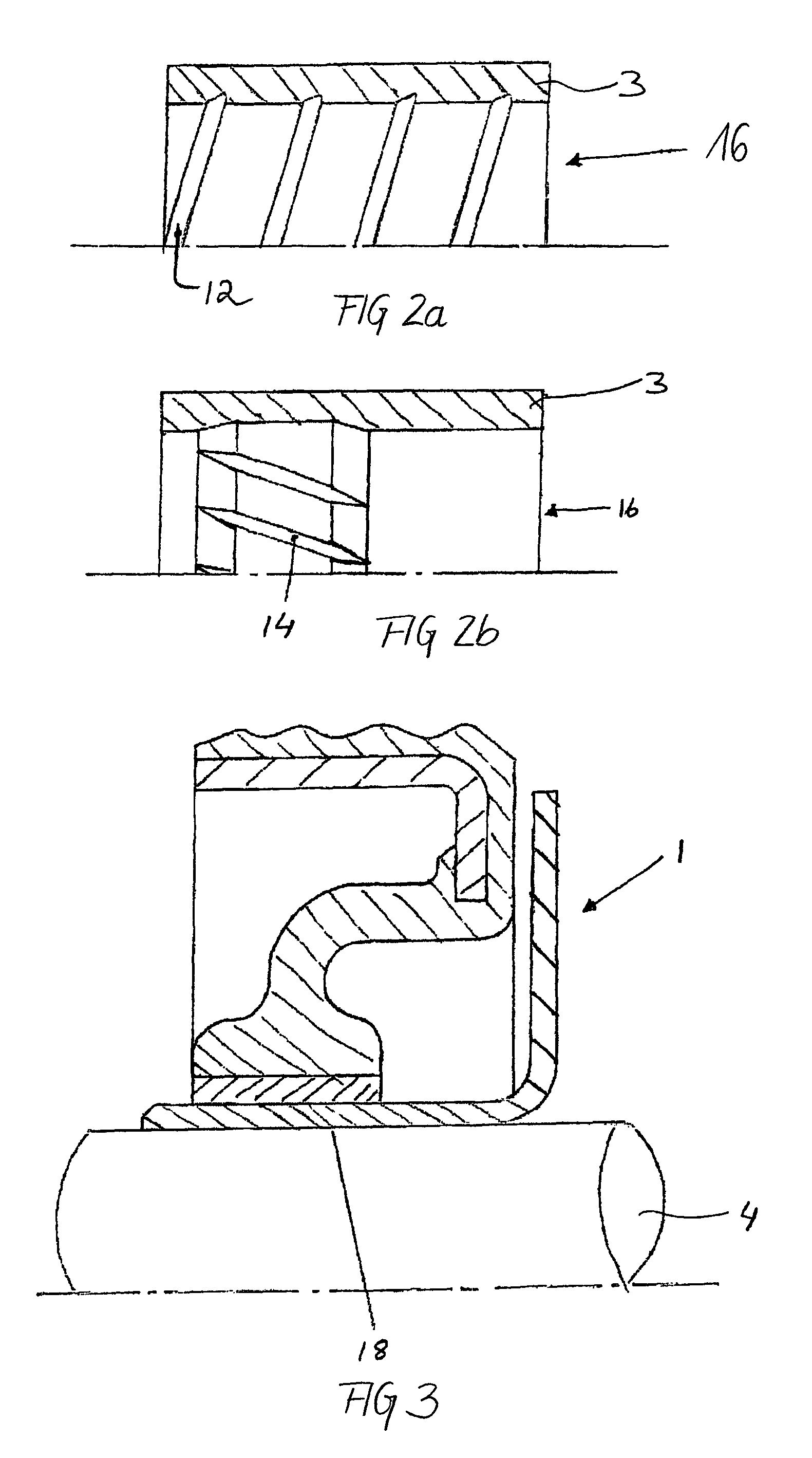
[0029]An example of a seal according to the invention is shown in FIG. 1a. The seal 1 comprises a sleeve-like section 3, which is adapted to be mounted around a rotatable component such as a shaft 4. The sleeve-like section 3 is connected to an outer casing 5 of the seal by means of a resilient section 7. The outer casing 5 is adapted to be mounted in e.g. a bore of a housing, and may (as shown) consist of a metal flange with a rubber outside diameter. Other variations are possible, such as a full rubber or a full metal casing. The outer casing 5 seals statically against the housing bore (not shown) and the sleeve-like section 3 provides dynamic sealing during rotation of the shaft 4. Such a seal may be used to seal a gap between a rotatable and a non-rotatable component and thereby retain fluid at a fluid side 6 of the seal in relation to an airside 9 of the seal.

[0030]According to the invention, low-friction dynamic sealing is obtained in that the sleeve-like section 3 is precisel...


PUM


Abstract

A seal to seal a gap between a rotatable component (4, 18) and a non-rotatable component comprises: A fastening section adapted to be fixedly mounted in relation to the non-rotatable component, a sleeve-like section (3) adapted to be mounted around the rotatable component (4, 18), a resilient section (7) between the sleeve-like and fastening section comprising an arcuate portion (8), and in an unmounted condition, the sleeve-like section (3) has an inner diameter, DSEAL, with a predefined magnitude relative to an outer diameter of the rotating component, DSHAFT, such that 0.9≦DSEAL / DSHAFT≦1.1.

Description

BACKGROUND OF THE INVENTION[0001]The present invention concerns a seal for sealing a gap between relatively rotatable components.[0002]Seal assemblies are widely applied to seal a gap between relatively rotatable components; for example, the gap between a revolving shaft or axle and the housing bore of a motor. The seals serve to retain lubricant within the motor and to exclude the entry of contaminants. Both of these aspects are important for proper running of the motor and the prevention of early failure. A typical seal comprises an outer casing to which a sealing element is bonded. Elastomeric materials, such as nitrile rubber, may be used for the sealing element. The outer casing seals statically against the housing bore. The sealing element seals against a counterface of the e.g. shaft and provides dynamic sealing during rotational conditions and static sealing during stationary conditions.[0003]Seals that are designed to retain oil or a low-viscosity fluid are generally spring...

Claims


Application Information

Patent Timeline
Patent Type & Authority Patents(United States)
IPC IPC(8): F16J15/32
CPCF16J15/3224
Inventor KURTH, JURGENWORSLEY, CLIFFORD ROLAND
Owner AB SKF
Why Eureka
Try Eureka