Virtual image display device and light guide plate therefor

a technology of virtual image and light guide plate, which is applied in the direction of optical light guide, instruments, optics, etc., can solve the problems of low light efficiency and cannot help but be relatively low, and achieve the effects of reducing internal reflection, high light efficiency and brightness variation

Active Publication Date: 2014-02-18
SEIKO EPSON CORP
View PDF11 Cites 5 Cited by
  • Summary
  • Abstract
  • Description
  • Claims
  • Application Information

AI Technical Summary

Benefits of technology

[0006]An advantage of same aspects of the invention is to provide a light guide plate for a virtual image display device capable of preventing the brightness variation and the picture variation and emitting the image light in a condition with relatively high light efficiency as virtual light, and a virtual image display device incorporating the light guide plate.

Problems solved by technology

Further, in the case of Patent Documents 1 and 2, since there is adopted the structure of making the light pass through the members for performing reflection a plurality of times when taking out the image light from the light guide plate by the reflection, the light efficiency cannot help but be relatively low.

Method used


Image

  • Virtual image display device and light guide plate therefor
  • Virtual image display device and light guide plate therefor
  • Virtual image display device and light guide plate therefor

Examples


first embodiment

[0031]Hereinafter, a light guide plate for a virtual image display device and a virtual image display device incorporating the light guide plate according to a first embodiment of the invention will be explained.

A. Structure of Light Guide Plate and Virtual Image Display Device

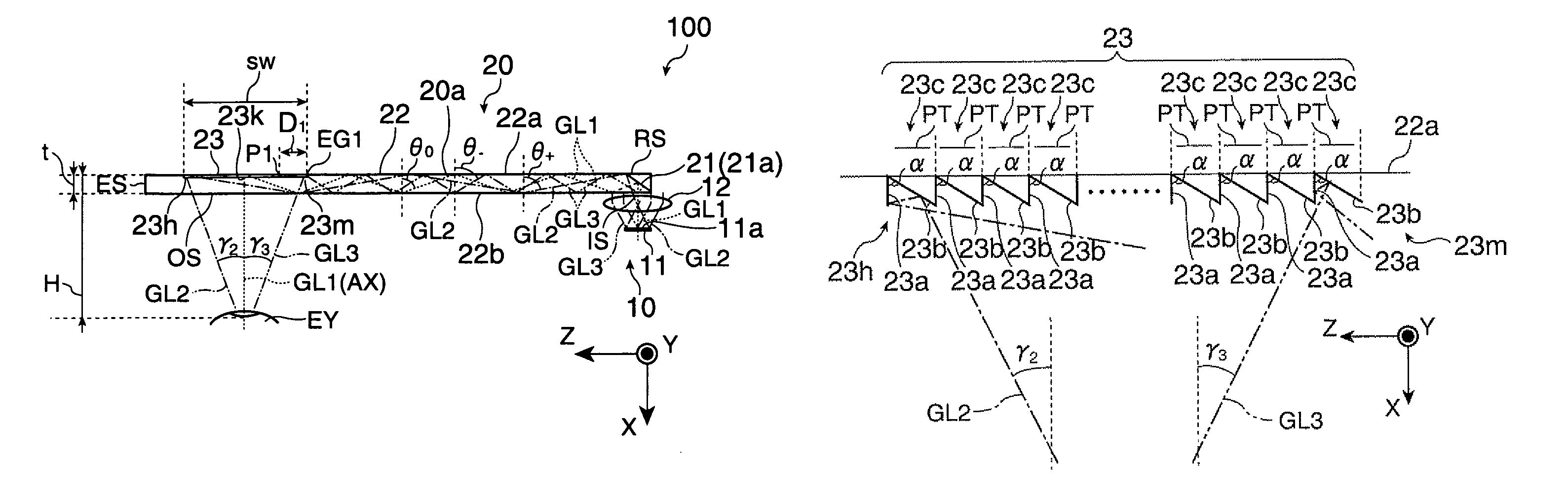
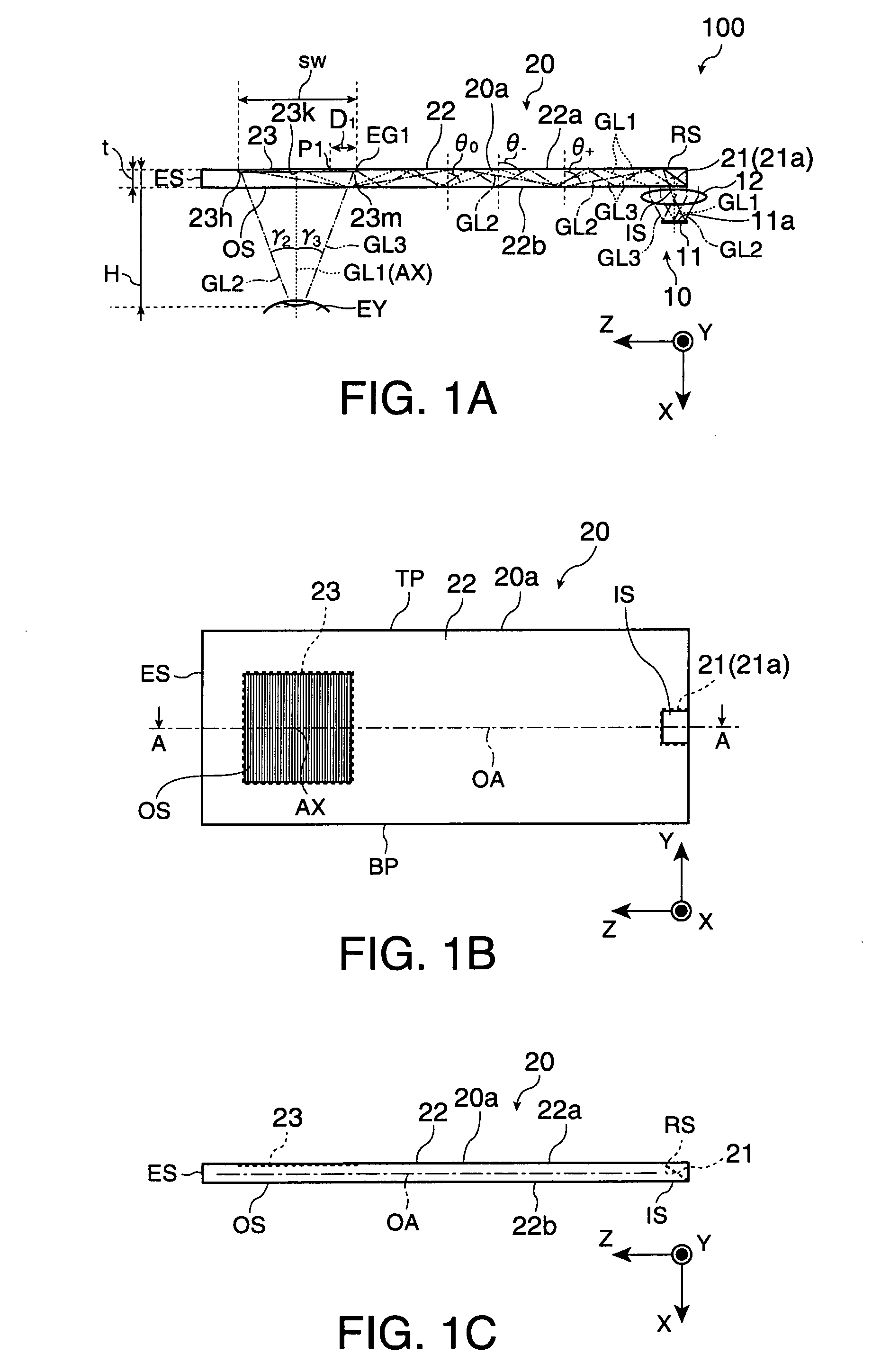
[0032]The virtual image display device 100 according to the present embodiment shown in FIG. 1A is to be applied to a head-mount display, and is provided with an image forming device 10 and a light guide plate 20 making a set. It should be noted that FIG. 1A corresponds to the A-A cross section of the light guide plate 20 shown in FIG. 1B.

[0033]The virtual image display device 100 is for making the observer recognize the image light of the virtual image, and at the same time, making the observer observe the external image in a see-through manner. Although the image forming device 10 and the light guide plate 20 are normally provided as a set to each of the right and left eyes of the observer, the set for the r...

second embodiment

E. Second Embodiment

[0074]A second embodiment obtained by modifying the first embodiment will hereinafter be explained with reference to FIGS. 7A and 7B. It should be noted that in the second embodiment shown in FIGS. 7A and 7B, the constituents denoted with the same reference symbols as in the light guide plate 20 shown in FIG. 1B and so on are equivalent to those explained in the first embodiment, unless particularly explained.

[0075]The light guide plate 120 according to the second embodiment shown in FIG. 7A is provided with black paint applied on the upper end surface TP, the lower end surface BP, and the termination surface ES. In other words, the upper end surface TP, the lower end surface BP, and the termination surface ES are the surfaces coated with the black paint, and block the component of the outside light, which can enter the image light to cause a ghost image, for example. Further, in the light guide plate 220 shown in FIG. 7B, the upper end surface TP, the lower end ...


PUM


Abstract

The image light entering the image take-out section is reflected by the first reflecting surface and the second reflecting surface in a two-stage manner. It is not only possible to make the light beam with a small total reflection angle out of the image light directly enter the side near to the light entrance section out of each of the reflecting units, but also to make the light beam with a large total reflection angle directly enter the side far from the light entrance section out of each of the reflecting units to thereby make it possible to take out the image light to the outside. Therefore, the image light is emitted as the effective virtual image light for the observer in the condition in which the brightness variation and the picture variation are prevented and a high light efficiency can be obtained.

Description

BACKGROUND[0001]1. Technical Field[0002]The present invention relates to a light guide plate used for a head-mount display or the like used while worn on the head, and a virtual image display device incorporating the light guide plate.[0003]2. Related Art[0004]In recent years, as a virtual image display device making it possible to form and observe a virtual image such as a head-mount display, there have been proposed various devices of a type of guiding the picture light from the display element to the pupils of the observer using a light guide plate. As such a light guide plate for a virtual image display device, there has been known a light guide plate, which guides the picture light using total reflection, reflects the picture light with a plurality of partial reflecting surfaces disposed in parallel to each other at a predetermined angle with a principal surface of the light guide plate, and thus outputs the picture light to thereby make the picture light reach the retinas of t...

Claims


Application Information

Patent Timeline
Patent Type & Authority Patents(United States)
IPC IPC(8): G02B27/01G02B27/14
CPCG02B6/0035G02B6/00G02B2027/0118G02B6/34G02B27/0172
Inventor TAKAGI, MASAYUKIMIYAO, TOSHIAKITOTANI, TAKAHIROKOMATSU, AKIRATAKEDA, TAKASHI
Owner SEIKO EPSON CORP
Why Eureka
Try Eureka