Bicycle control system having a value generating unit

a control system and value generation technology, applied in the direction of cycle equipment, process and machine control, instruments, etc., can solve the problems of not shifting the gear position correctly, the receiver may not receive the signal, and increasing the likelihood that at least one transmission will occur during a shift switch operation

Active Publication Date: 2014-02-18
SHIMANO INC
View PDF15 Cites 57 Cited by
  • Summary
  • Abstract
  • Description
  • Claims
  • Application Information

AI Technical Summary

Benefits of technology

[0009]One object of the present invention is to provide an improved bicycle wireless control system.
[0010]Another object of the present invention is to provide an improved bicycle wireless control system for controlling front and rear derailleur systems. The foregoing objects can basically be attained by providing a bicycle control system that mainly comprises at least one user input member, a value generating unit, a wireless transmitter and a wireless receiver. The value generating unit includes a memory component that at least temporarily stores a generated value. The value generating unit updates the generated value that was memorized in accordance with the at least one user input member was operated. The wireless transmitter periodically transmits control signals that are indicative of the generated value. The wireless receiver receives the control signals from the wireless transmitter.

Problems solved by technology

Furthermore, even if the transmitter correctly transmits the signal, noise or other disturbances may interfere with the signal and thus, the receiver may not receive the signal.
If any of these situations occur, the receiver will not receive the correct shifting signal and thus, will not shift the gear position correctly.
Shortening the time between prescribed transmission periods can potentially reduce the possibility that operation of a shift switch will be brief enough to occur between prescribed transmission periods, thus increasing the likelihood that at least one transmission will occur during a shift switch operation.
Also, shortening the time between prescribed transmission periods increases the number of transmissions, thus increasing the likelihood that the receiver will receive a transmission indicating operation of a shift switch even in the presence of noise or other interferences.
However, increasing the number of transmissions increases the electric power consumption by the transmitter, thus decreasing the efficiency of the control system.

Method used


Image

  • Bicycle control system having a value generating unit
  • Bicycle control system having a value generating unit
  • Bicycle control system having a value generating unit

Examples


Embodiment Construction

[0023]Selected embodiments of the present invention will now be explained with reference to the drawings. It will be apparent to those skilled in the art from this disclosure that the following descriptions of the embodiments of the present invention are provided for illustration only and not for the purpose of limiting the invention as defined by the appended claims and their equivalents.

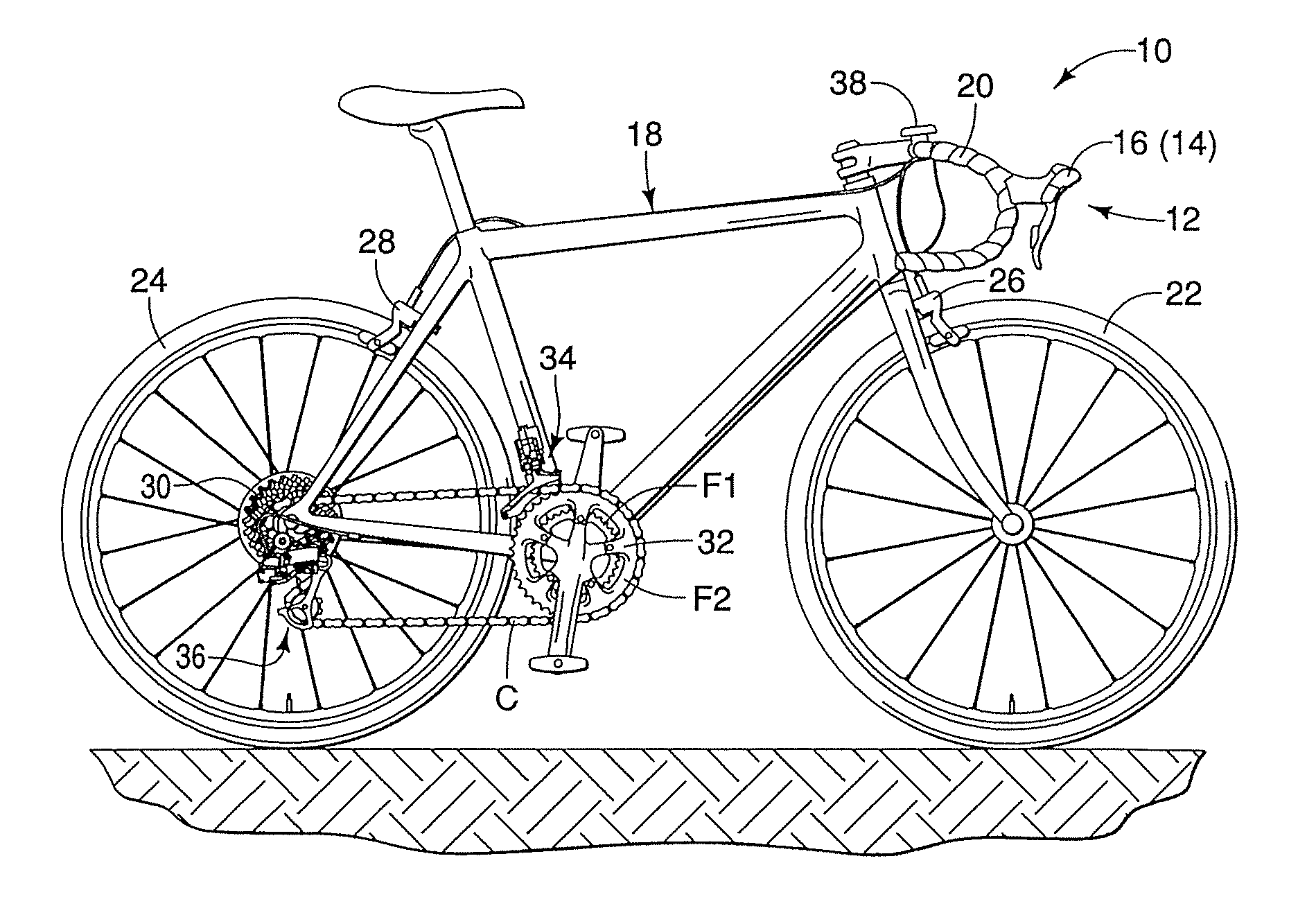
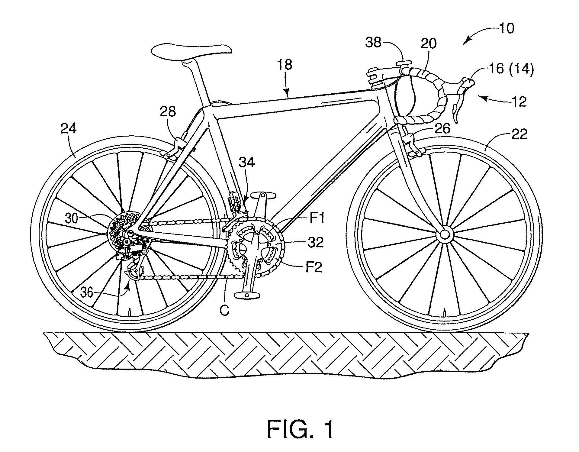
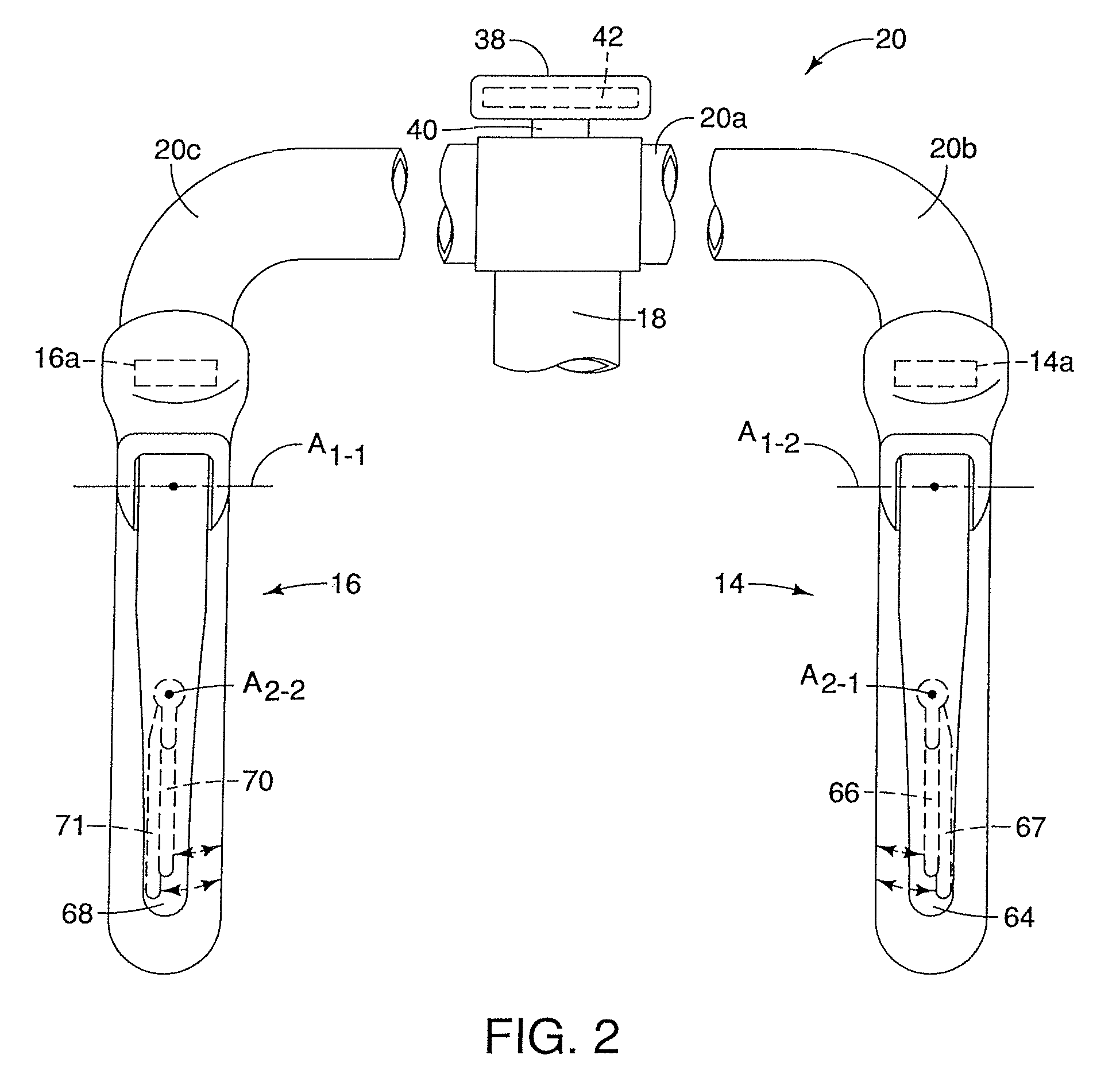
[0024]Referring initially to FIG. 1, a bicycle 10 is illustrated in accordance with a disclosed embodiment. The bicycle 10 has an electrically powered wireless bicycle control system 12 that includes a front shifter 14 with a wireless controller 14a and a rear shifter 16 with a wireless controller 16a as shown in FIGS. 2-4 and described in greater detail below.

[0025]The bicycle 10 includes, among other things, a bicycle frame 18 with a handlebar 20, a front wheel 22, a rear wheel 24, a front brake 26 and a rear brake 28. As shown in FIGS. 2 to 4, the handlebar 20 includes a central portion 20a, a l...


PUM


Abstract

A bicycle control system includes at least one user input member, a value generating unit, a wireless transmitter and a wireless receiver. The value generating unit includes a memory component that at least temporarily stores a generated value. The value generating unit updates the generated value that was memorized in accordance with the at least one user input member was operated. The wireless transmitter periodically transmits control signals that are indicative of the generated value. The wireless receiver receives the control signals from the wireless transmitter.

Description

BACKGROUND[0001]1. Field of the Invention[0002]This invention generally relates to a bicycle control system. More specifically, the present invention relates to a bicycle control system that wirelessly transmits control signals to control components on the bicycle.[0003]2. Background Information[0004]Bicycle control systems exist that wirelessly control bicycle components, such as the bicycle derailleur systems. In an example of such a control system, an upshift signal (e.g., a high signal) is transmitted continuously during the time that an upshift switch is operated, and a downshift signal (e.g., a pulse signal) is transmitted continuously during the time that a downshift switch is operated. However, it can be appreciated that the amount of electric power needed to output a high signal or pulse signal continuously when the upshift switch or downshift switch is operated is much greater than the amount of electric power needed to output such signals intermittently.[0005]Accordingly,...

Claims


Application Information

Patent Timeline
Patent Type & Authority Patents(United States)
IPC IPC(8): G06F7/00
CPCB62M25/08B62K23/06
Inventor KITAMURA, SATOSHI
Owner SHIMANO INC
Why Eureka
Try Eureka