Spinal decompression device and method of use

a decompression device and spine technology, applied in the field of spine decompression devices, can solve the problems of complex, cumbersome, difficult to carry, etc., and achieve the effect of reducing the length of the first segment, increasing the second segment, and adjusting the tension in the effective tension length segmen

Active Publication Date: 2014-02-25
FISHER JEFF
View PDF17 Cites 10 Cited by
  • Summary
  • Abstract
  • Description
  • Claims
  • Application Information

AI Technical Summary

Benefits of technology

[0011]According to various embodiments, the anchor object may be a door handle. The method may further include adjusting the tension in the effective tension length segment by changing a length of the first or second load line. In an embodiment, the first load line includes a first segment and a second segment. The first segment extends from the elastomeric member to the buckle and the second segment extends from a buckle. The method may further include pulling upon the second segment in a direction away from the buckle to reduce a length of the first segment and increase a length of the second segment. The adjustment element may be sized and configured to adjust the tension in the effective tension length segment by applaying a force along the first or second load lines in a direction towards the head attachment end. There may be provided a release line that is attached to the second load line, and the method may include pulling upon the release line in a direction toward the head attachment end to decrease the tension in the second load line at the head attachment end.

Problems solved by technology

Most of such devices, however, are complex, cumbersome, not readily portable, or require trained healthcare personnel to place the device on the patient and administer treatment.

Method used


Image

  • Spinal decompression device and method of use
  • Spinal decompression device and method of use
  • Spinal decompression device and method of use

Examples


Embodiment Construction

[0019]The detailed description set forth below in connection with the appended drawings is intended as a description of the presently preferred embodiments of the invention, and is not intended to represent the only form in which the present devices may be developed or utilized. It is to be understood, however, that the same or equivalent functions may be accomplished by different embodiments that are also intended to be encompassed within the spirit and scope of the invention. It is further understood that the use of relational terms such as first, second, and the like are used solely to distinguish one from another entity without necessarily requiring or implying any actual such relationship or order between such entities.

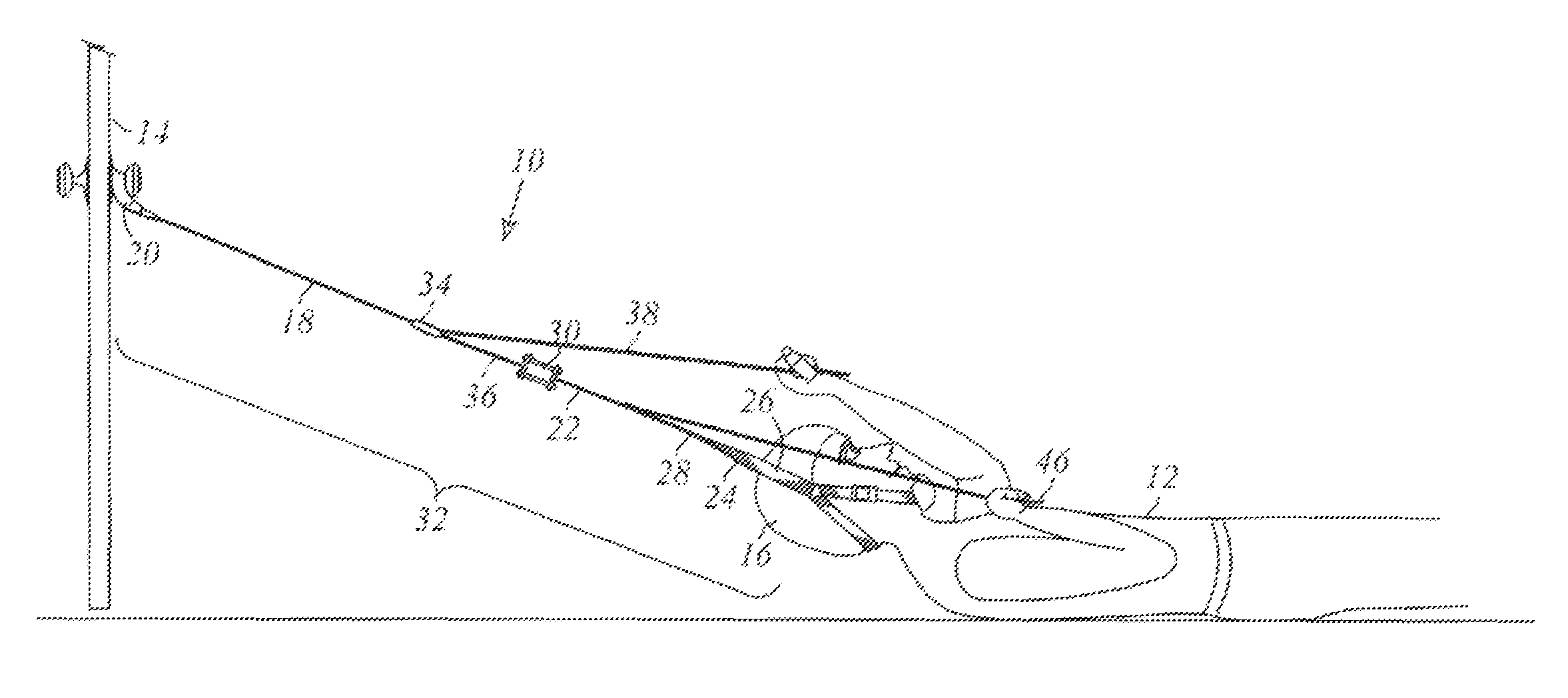
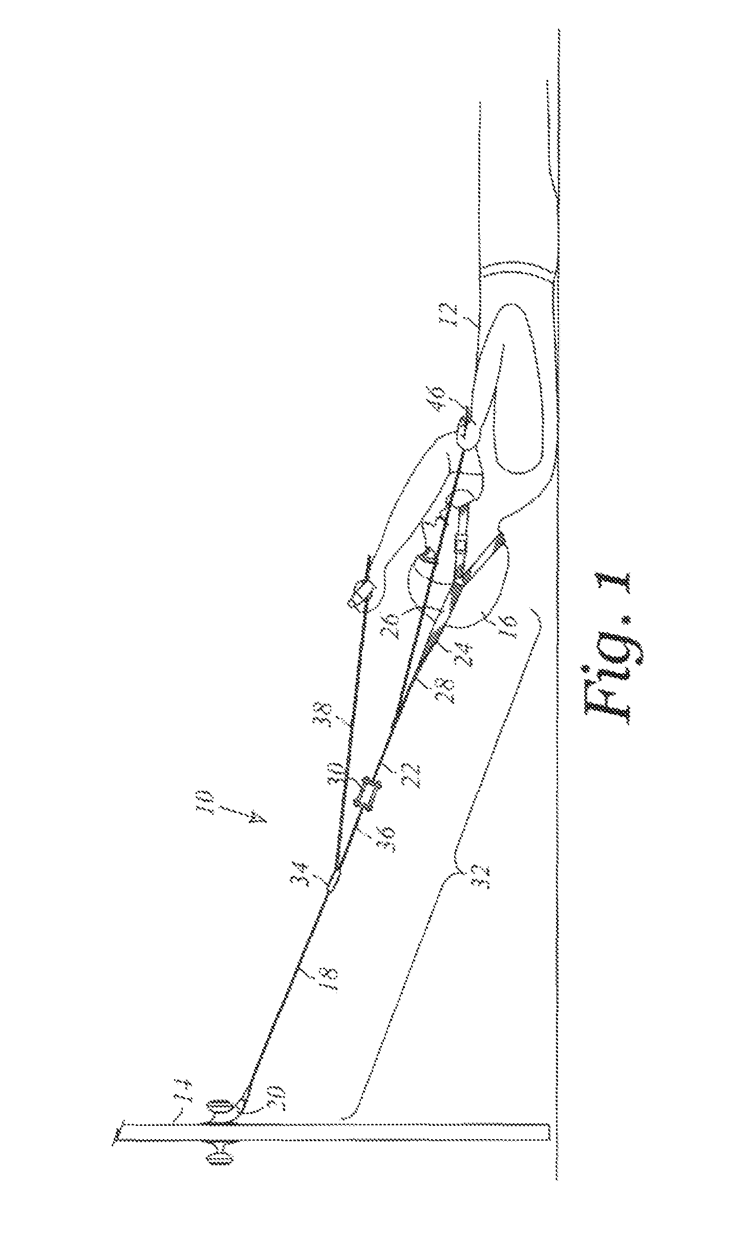
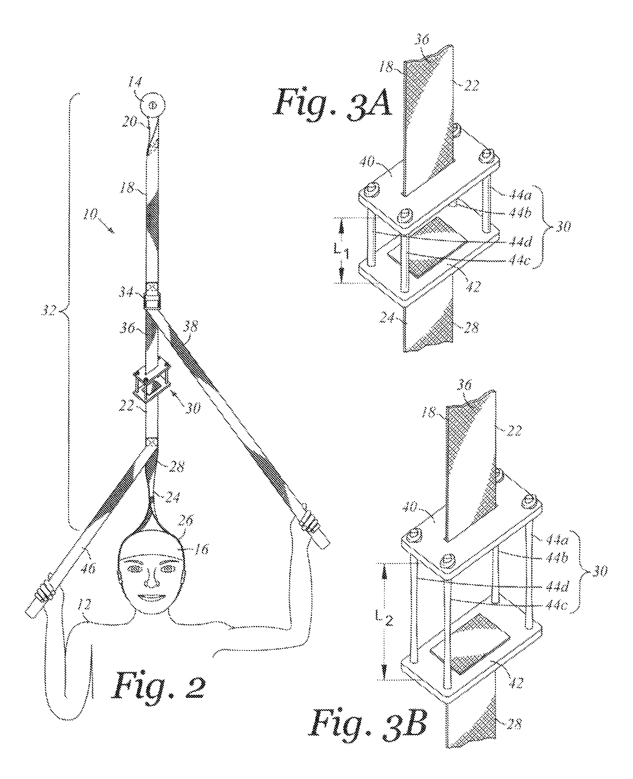
[0020]Referring now FIG. 1 there is depicted a perspective view of a perspective view of a spinal decompressing device 10 as being used by a patient 12 and attached to an anchor object 14 according to an aspect of the invention. FIG. 2 depicts a top view of the p...


PUM


Abstract

There is provided a device for use with a patient. The device includes a first load line including an anchor attachment end and a first inline end. The anchor attachment end is sized and configured to be attachable in a terminating manner to an anchor object. The device further includes a second load line including a head attachment end and a second inline end. The head attachment end is sized and configured to attach to a head of the patient. The device further includes an elastomeric member disposed between and attached to the first and second inline ends. The elastomeric member has a significantly lower linear elastic modulus than each of the first and second load lines. The device further includes an adjustment element sized and configured to adjust the tension in an effective tension length of the device.

Description

CROSS-REFERENCE TO RELATED APPLICATIONS[0001]Not Applicable.STATEMENT RE: FEDERALLY SPONSORED RESEARCH / DEVELOPMENT[0002]Not ApplicableBACKGROUND[0003]1. Technical Field[0004]The present disclosure generally relates to spinal decompression devices, and more particularly, to a spinal device including an elastomeric element.[0005]2. Related Art[0006]Spinal decompression therapy is a non-surgical, non-invasive treatment for certain types of chronic back pain that works by slowly and gently stretching the spine, taking pressure off compressed discs and vertebrae. A myriad of devices have been developed for providing decompression or applying traction to the human spine. Most of such devices, however, are complex, cumbersome, not readily portable, or require trained healthcare personnel to place the device on the patient and administer treatment. Moreover, some devices require the patient to actively apply a force or counter-force with the hands, legs or feet. This is counter to the decom...

Claims


Application Information

Patent Timeline
Patent Type & Authority Patents(United States)
IPC IPC(8): A61F5/00
CPCA61H2201/0157A61H2201/1607A61H1/0292A61H2201/1664A61H2201/1253A61H1/0296A61H2201/1652A61F5/00
Inventor FISHER, JEFF
Owner FISHER JEFF
Why Eureka
Try Eureka