Apparatus and method for measuring energy in a laser beam

a laser beam and energy measurement technology, applied in the field of laser beam energy measurement sensors, can solve the problems of affecting the quality of laser beams,

Inactive Publication Date: 2014-02-25
UNITED STATES OF AMERICA
View PDF8 Cites 14 Cited by
  • Summary
  • Abstract
  • Description
  • Claims
  • Application Information

AI Technical Summary

Problems solved by technology

The conventional techniques used to measure energy of a laser beam typically utilize costly technologies such as pyroelectric based sensors.
Such sensors are costly to manufacture and can easily command prices of around one thousand dollars per unit.
However, the absorber must be in close contact with the thermopile, and damage to the absorbing surface from the impinging laser will also likely damage the underly...

Method used


Image

  • Apparatus and method for measuring energy in a laser beam
  • Apparatus and method for measuring energy in a laser beam
  • Apparatus and method for measuring energy in a laser beam

Examples


Embodiment Construction

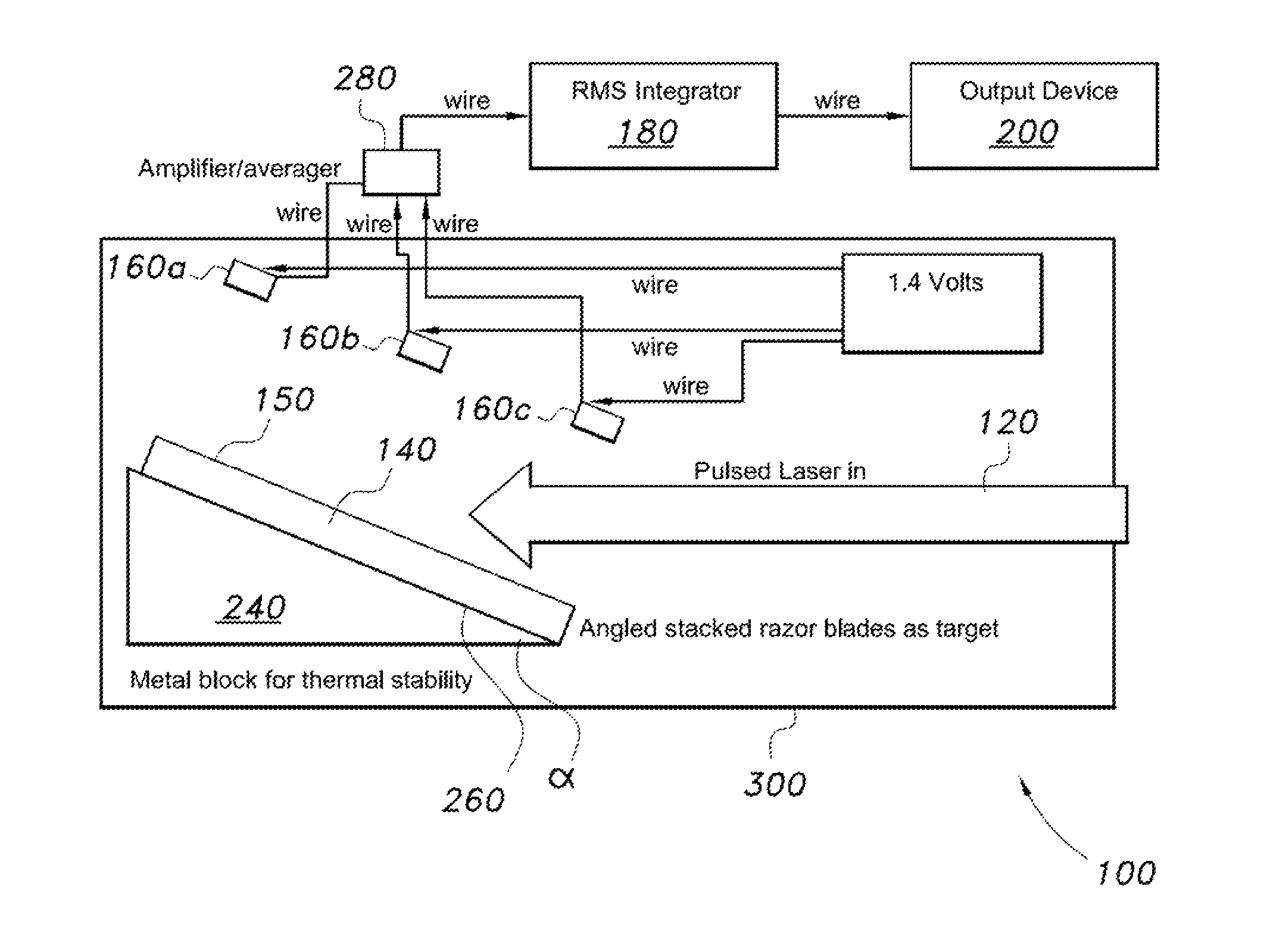
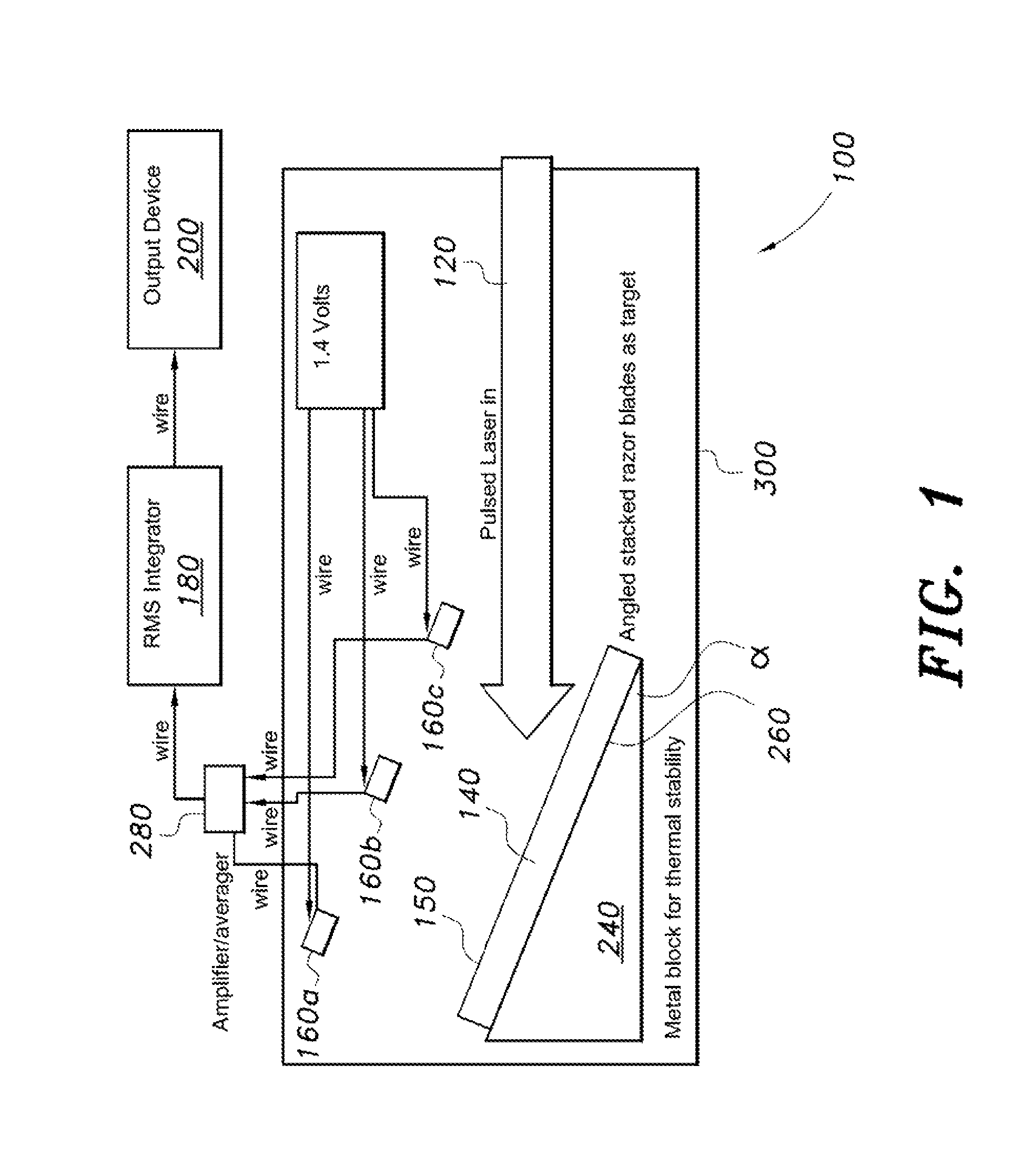
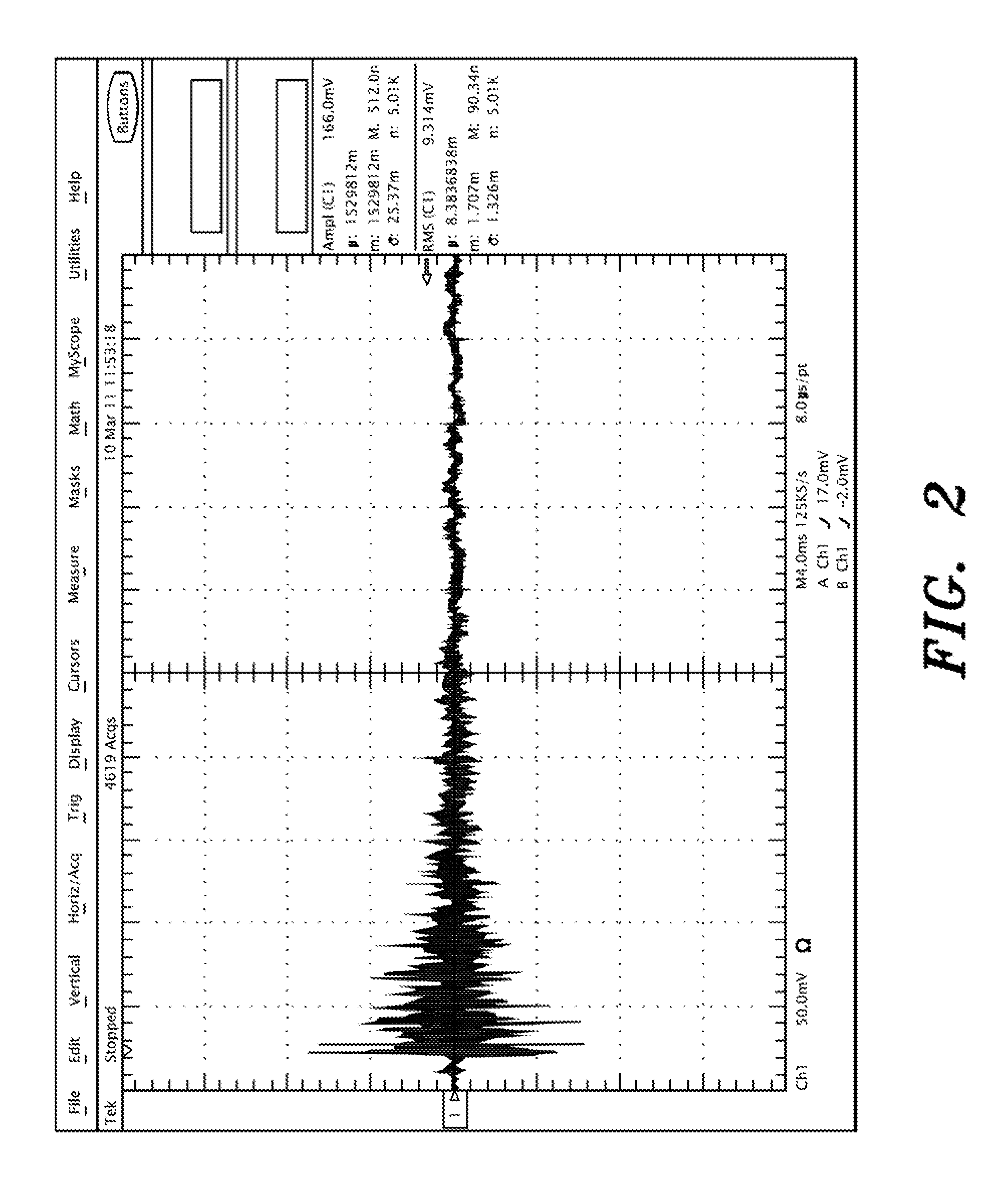
[0014]This invention is directed to sensors for measuring the energy of a pulsed laser beam. More specifically, the invention is a sensor that exploits the photoacoustic effect to measure the energy in a laser beam. The photoacoustic effect occurs when light from a source, such as a laser, is absorbed by a material and the absorbed light is rapidly converted to heat which, is then dissipated to the surroundings. Heat transfer into the gas phase is rapidly converted into the translational motion of gas molecules, which is observed as an increase in pressure. If the light source, such as a laser, is modulated or pulsed at a given frequency then the result is an increase and decrease in pressure at the same frequency as the modulation of the light source. This oscillation of pressure is a sound wave. The intensity, or amplitude, of the pressure waves (sound) is directly proportional to the intensity of the light source and the absorption coefficient of the absorbing material. Thus, the...


PUM


Abstract

A laser energy sensor and methodology for measuring laser energy in a laser beam by photoacoustic means. Laser energy is converted into acoustic energy which is then measured and converted to an energy reading corresponding to the energy of a laser beam.

Description

GOVERNMENT INTEREST[0001]The invention described herein may be manufactured, licensed, and used by or for the U.S. Government.FIELD OF THE INVENTION[0002]This invention relates to sensors for measuring the energy of a laser beam. More specifically, the invention is a sensor and methodology that employs a photoacoustic effect to measure the energy in a pulsed laser beam.BACKGROUND OF THE INVENTION[0003]The conventional techniques used to measure energy of a laser beam typically utilize costly technologies such as pyroelectric based sensors. Pyroelectric based sensors rely on the ability of certain materials to generate a temporary voltage when they are heated or cooled. Such sensors are costly to manufacture and can easily command prices of around one thousand dollars per unit.[0004]Prior art thermopiles are based on thermocouples in series which generate a voltage based on the amount of heating caused by absorption of the laser. However, the absorber must be in close contact with th...

Claims


Application Information

Patent Timeline
IPC IPC(8): G01J1/42
CPCG01J1/4257G01N29/2425G01N29/11G01N29/2418
Inventor CABALO, JERRY, B.
Owner UNITED STATES OF AMERICA
Why Eureka
Try Eureka