
Image reading apparatus

a reading apparatus and image technology, applied in the direction of electrical devices, pictoral communication, etc., can solve the problems of image being read in a tilted state, the area at both ends in the lengthwise direction of the carriage, and the risk of tilting the image, so as to achieve the effect of suppressing tilting

Active Publication Date: 2014-02-25
SEIKO EPSON CORP
View PDF17 Cites 8 Cited by
  • Summary
  • Abstract
  • Description
  • Claims
  • Application Information

AI Technical Summary

Benefits of technology

This configuration effectively suppresses tilting of the reading carriage and sensor, ensuring accurate image reading by maintaining the carriage's alignment and reducing sliding load, even when the pinion rotates.

Problems solved by technology

However, in this case, momentum is generated central to the point of engagement between the pinion and the rack, and there is thus a problem in that areas at both ends in the lengthwise direction of the carriage, which is orthogonal to the main scanning direction, will become tilted.
As a result, the reading sensor will also become tilted when the carriage is moving, resulting in the risk of images being read in a tilted state.

Method used


Image

  • Image reading apparatus
  • Image reading apparatus
  • Image reading apparatus

Examples


Embodiment Construction

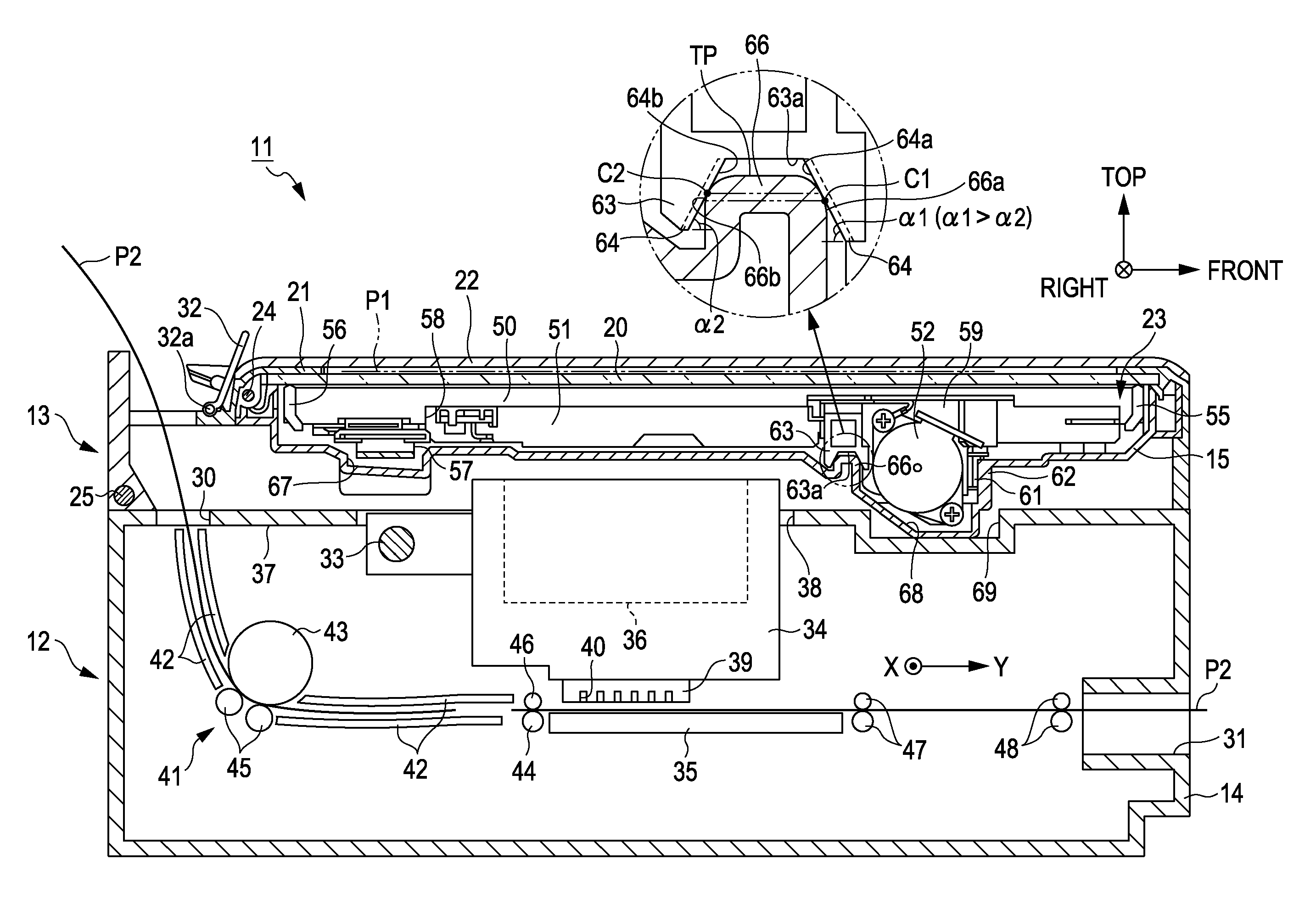
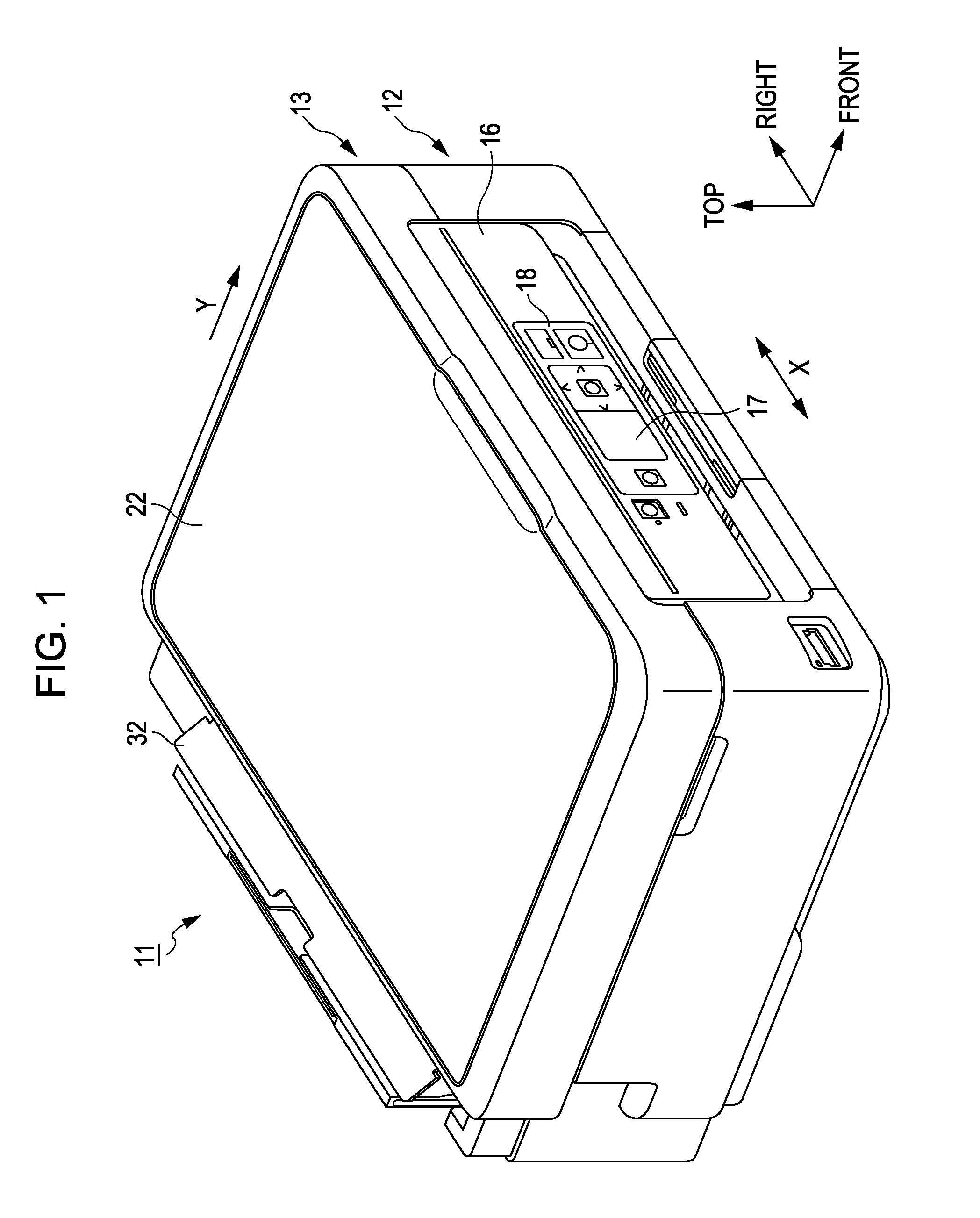
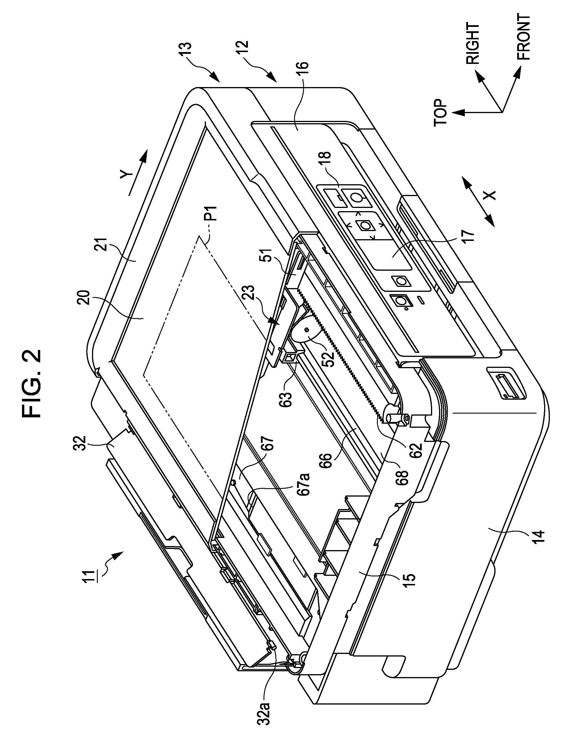
[0027]A complex machine provided with an image reading unit, embodying the image reading apparatus according to the invention, will be described hereinafter. Note that the terms “depth direction”, “horizontal direction”, and “vertical direction” as used in the descriptions hereinafter refer respectively to the depth direction, horizontal direction, and vertical direction indicated by the arrows in the drawings. Furthermore, with respect to the arrows in the drawings that indicate the top, right, and front directions, a dot within a circle indicates an arrow moving from the rear to the front in the depth direction of the paper itself (in a drawing in which the tip of the arrow is viewed from the front), whereas an × within a circle indicates an arrow moving from the front to the rear in the depth direction of the paper itself (in a drawing in which the base (feather) of the arrow is viewed from the rear).

[0028]As shown in FIG. 1, a complex machine 11 includes a recording unit 12 that...


PUM


Abstract

An image reading apparatus comprises: a guide portion that is linked to a driving portion and extends so as to guide the movement of a reading carriage; a guide rail that guides the reading carriage while supporting the reading carriage; and an interlocking portion that is provided in the reading carriage, has a first sliding surface that makes contact with the guide rail on the side of the guide rail facing the guide portion and a second sliding surface that makes contact with the guide rail on the side of the guide rail that is on the opposite side as the guide portion. The position at which the first sliding surface of the interlocking portion makes contact with the guide rail is lower on the guide rail than the position at which the second sliding surface of the interlocking portion makes contact with the guide rail.

Description

BACKGROUND[0001]1. Technical Field[0002]The present invention relates to image reading apparatuses such as flatbed scanners.[0003]2. Related Art[0004]Thus far, there have been scanners, which are a type of image reading apparatus, in which a carriage that moves in the main scanning direction supports a reading sensor for reading an image of a document, and a motor for moving the carriage is provided in the scanner (for example, see JP-A-2004-54283).[0005]In the scanner disclosed in JP-A-2004-54283, a pinion that is rotated by the motor is mounted in the carriage, and a rack that engages with the pinion is provided in the main apparatus unit itself. Accordingly, the carriage moves in the main scanning direction as a result of the motor being driven when the pinion and the rack are engaged with each other.[0006]Incidentally, with such a carriage, there are cases where the pinion separates from the rack while the pinion is rotating. Accordingly, with the scanner disclosed in JP-A-2004-...

Claims


Application Information

Patent Timeline
Patent Type & Authority Patents(United States)
IPC IPC(8): H04N1/04
CPCH04N1/1017H04N2201/0442H04N2201/0458H04N2201/0094H04N1/103H04N1/00559H04N1/1039H04N2201/0428
Inventor HARA, KOJIMIYAGAWA, TETSUYAKIMURA, NAOMI
Owner SEIKO EPSON CORP
Learn More