Method and system for test vector generation

a test vector and vector technology, applied in the direction of electronic circuit testing, specific program execution arrangements, program control, etc., can solve the problems of unavoidable test of integrated circuit chips, unavoidable test of several products, and significant issues in quality control and testing, so as to eliminate duplication of test vectors, reduce manual intervention, and eliminate the effect of test vector duplication

Active Publication Date: 2014-02-25
RAJARAO RAVISHANKAR +1
View PDF17 Cites 2 Cited by
  • Summary
  • Abstract
  • Description
  • Claims
  • Application Information

AI Technical Summary

Benefits of technology

[0014]Yet another object of the embodiments herein is to provide a system and method which reduces the extent of manual intervention during the execution of verification parameters of the chip.
[0025]According to an embodiment herein, the Execution PCs receives the Real Handle (RH) from the DCMS server and maps the real handle with a local Virtual Handle (VH) due to which the RH is hidden from user and the access to the server is made secure.

Problems solved by technology

Currently for the chip vendor industry, it is unavoidable to perform various tests on integrated circuit chips with different specifications to verify whether the operation of the design is correct or not.
Therefore, the quality control and test for several products has become a significant issue in the chip vending industry.
The chip vending companies are facing an unprecedented challenge of balancing the design realization time, cost and the product market life of the integrated circuit (IC) chips.
The overall process requires user intervention at regular time intervals and also consumes a lot of time.
Further the existing techniques do not provide for automatic generation of aligned constraints and coverage objects to monitor and report the quality of the vectors generated.
However the existing constrained random verification technology includes various limitations such as running several regression of constraint solver to cover the entire state space.

Method used


Image

  • Method and system for test vector generation
  • Method and system for test vector generation
  • Method and system for test vector generation

Examples


Embodiment Construction

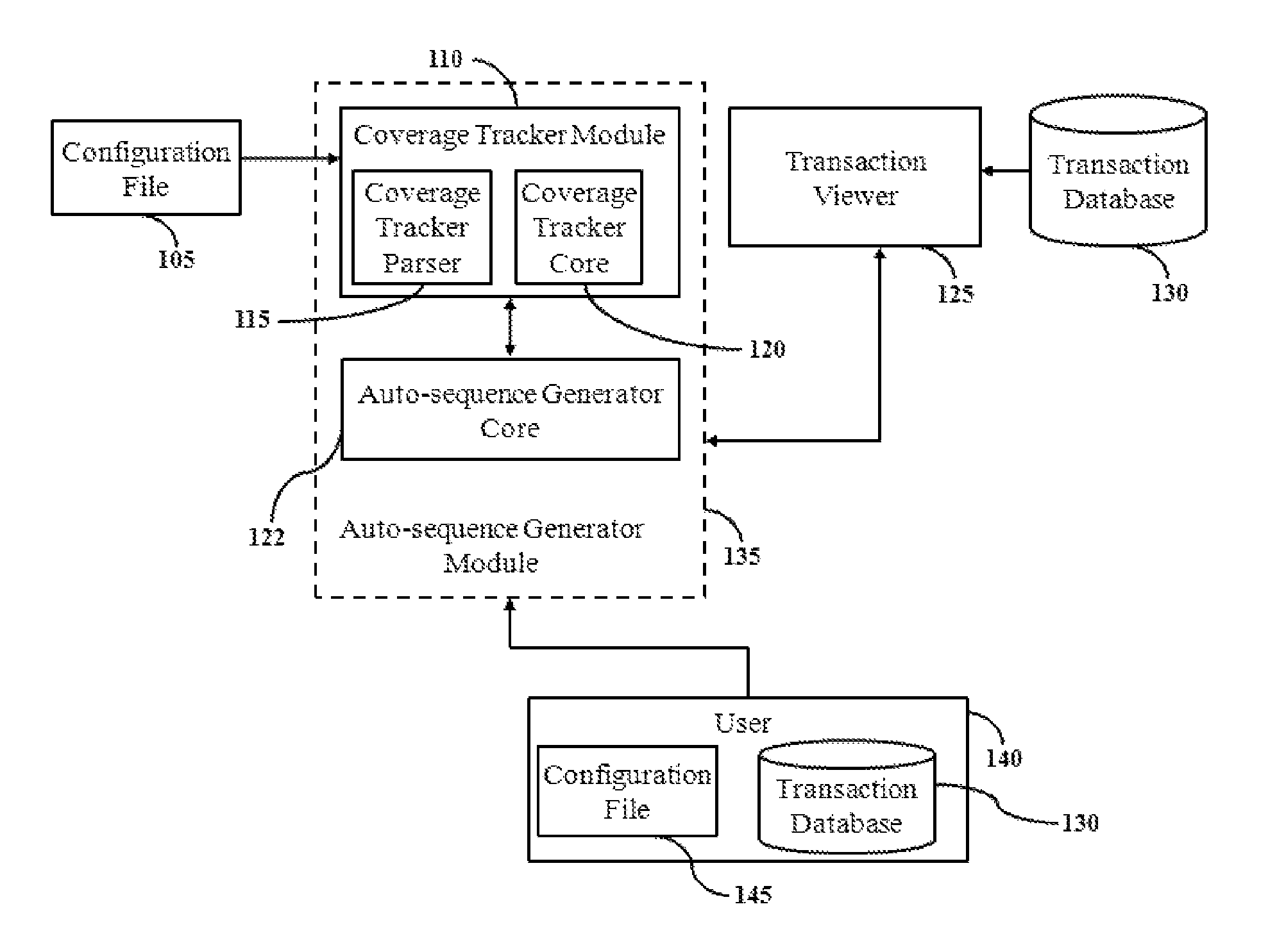
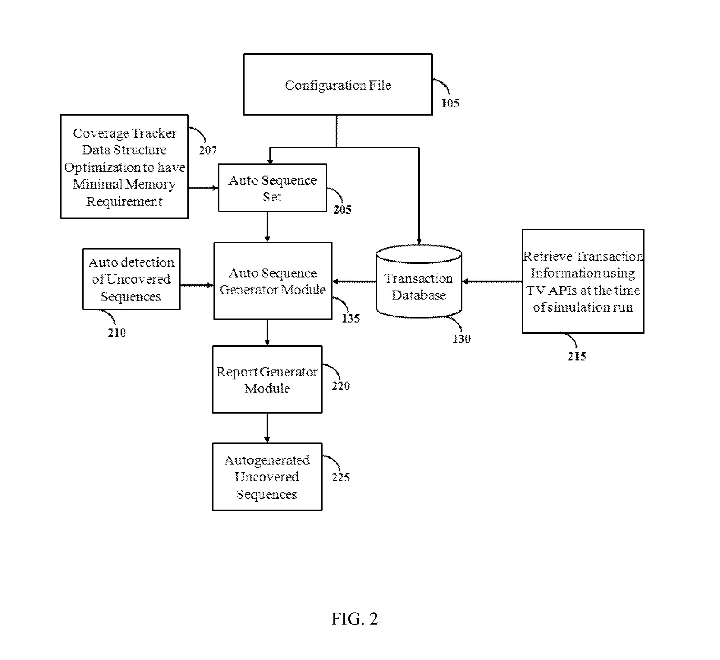
[0042]In the following detailed description, a reference is made to the accompanying drawings that form a part hereof, and in which the specific embodiments that may be practiced is shown by way of illustration. These embodiments are described in sufficient detail to enable those skilled in the art to practice the embodiments and it is to be understood that the logical, mechanical and other changes may be made without departing from the scope of the embodiments. The following detailed description is therefore not to be taken in a limiting sense.

[0043]The primary object of the embodiments herein is to provide a system and method for automatically generating a unique set of vector for each of the integrated circuit chip in a plurality of Execution PCs. The method includes generating an Executable Verification Plan (EVP) pertaining to the configurations associated with the plurality of integrated circuit chips and automatically verifying configurations associated with a plurality of in...


PUM


Abstract

The various embodiments of the present invention provide a method for automatically generating a unique set of test vectors for verifying design intent of integrated circuit chips. The method includes obtaining configuration parameters associated with a plurality of integrated circuit chips, generating an Executable Verification Plan pertaining to the configuration parameters of a plurality of integrated circuit chips in one or more execution PCs (EPs), creating a plurality of data structures corresponding to the configuration parameters, communicating the data structures created to a DCMS server, mapping the data structures of the Execution PCs with one or more data structures present in a database of the DCMS server, customizing the executable verification plan based on changes in the configurations of the integrated circuit chips, generating a unique set of test vectors based on mapping of the data structures and performing automatic design verification of the plurality of integrated circuit chips.

Description

CROSS-REFERENCE TO RELATED APPLICATIONS[0001]The present application claims priority to provisional application Ser. No. 85 / CHE / 2011 filed on Jan. 11, 2011, and that application is incorporated in its entirety at least by reference.BACKGROUND[0002]1. Technical Field[0003]The embodiments herein generally relate to test vector generation systems and methods and more particularly relates to automated generation of unique test vectors for verification of integrated circuit chip configuration.[0004]2. Description of the Related Art[0005]Currently for the chip vendor industry, it is unavoidable to perform various tests on integrated circuit chips with different specifications to verify whether the operation of the design is correct or not. Therefore, the quality control and test for several products has become a significant issue in the chip vending industry. The chip vending companies are facing an unprecedented challenge of balancing the design realization time, cost and the product mar...

Claims


Application Information

Patent Timeline
Patent Type & Authority Patents(United States)
IPC IPC(8): G01R31/28G06F11/00
CPCG01R31/318342
Inventor RAJARAO, RAVISHANKAREDNAD, CHINTHANA
Owner RAJARAO RAVISHANKAR
Why Eureka
Try Eureka