Arm-rest adjustable in inclination, in particular for vehicles

a technology of armrests and inclinations, which is applied in the direction of seating furniture, monocoque constructions, domestic objects, etc., can solve the problems of limiting the adjustment possibilities, unable to increase the number of teeth, and the inability to finely adjust the inclination, so as to achieve the effect of easy and economical production

Inactive Publication Date: 2014-03-04
CLERPREM
View PDF18 Cites 11 Cited by
  • Summary
  • Abstract
  • Description
  • Claims
  • Application Information

AI Technical Summary

Benefits of technology

[0014]Consequently, purpose of the present invention is to eliminate the drawbacks of the aforementioned known art, making available an adjustable arm-rest, in particular for vehicles, which permits a finer adjustment of the inclination of the support plane it defines.
[0016]A further purpose of the present invention is to make available an adjustable arm-rest, which is structurally safe and solid.
[0017]A further purpose of the present invention is to make available an adjustable arm-rest, which is easy and economical to produce.

Problems solved by technology

A first limit of the adjustable arm-rests described above lies in the impossibility of fine adjustment of the inclination.
Once the excursion angle has been fixed (between the maximum and minimum inclination) for reasons of construction and solidity, it is not possible to increase the number of teeth.
This significantly limits the adjustment possibilities, thereby making the arm-rest not always adaptable to the user's needs, to the detriment of perceived comfort.
A second limit is the noise of the system for adjusting the arm-rest.
The steps of the ratchet device produce noises which may be annoying, giving the idea of malfunctioning and poor product quality.
A third limit is associated with the risk that the ratchet device, on account of wear or construction defects of the toothed portions, may not function correctly.
It may happen in fact that in some adjustment positions, the movable part of the arm-rest does not remain stable, or that the movable part suddenly falls downwards.

Method used


Image

  • Arm-rest adjustable in inclination, in particular for vehicles
  • Arm-rest adjustable in inclination, in particular for vehicles
  • Arm-rest adjustable in inclination, in particular for vehicles

Examples


first embodiment

[0084]More specifically, again with reference to the aforesaid first embodiment of the invention, the releasing means comprise a toothed annular portion 30 made on the main portion 11 of the shaft 10, in a distal position in relation to the extremal portion 12. Such toothed portion 30 is positioned inside the cylindrical seat 6 defined by the first bush 4 of the fixed part 2 in a distal position in relation to the freewheeling bearing 20.

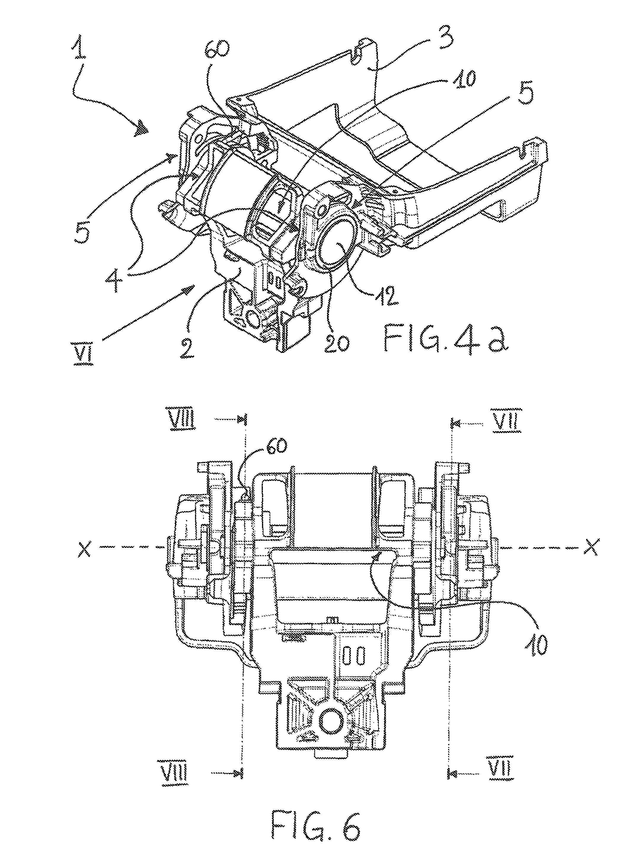
[0085]The releasing means comprise, in addition, two toothed movable pawls 31, pivoting on the fixed part 2 of the arm-rest 1 and positioned inside the cylindrical seat 6 in which the toothed annular portion 30 of the shaft 10 is positioned. The two pawls 31 are positioned laterally on the shaft 10 in opposite positions so as to act on the latter like a vice and are kept engaged to the toothed portion 30 by elastic means 32, as shown in FIG. 8.

[0086]The releasing means comprise a manually operated mechanism 60 for moving the two pawls 31. The mechan...

second embodiment

[0095]The releasing means foreseen in this second embodiment do not require direct manual operation by a user, but are automatically activated by the movement of the movable part 3 itself of the arm-rest 1, as will be clarified further on in the description. On the one hand this simplifies the action of the user, but on the other does not allow liberating the downward movement of the movable part 3 in whatever position it is in. In fact this way the movable part needs to be raised first in order to liberate the downward movement.

[0096]Functionally, in the same way as foreseen in the first embodiment, the releasing means are able to alternately assume a first operative position, wherein they prevent rotation of the shaft 10 in relation to the fixed part 2, and a second operative position wherein they let the shaft 10 free to rotate in relation to the fixed part 2.

[0097]When the releasing means are in the first operative position the rotation of the movable part 3 can only occur in th...

third embodiment

[0119]More in detail, continuing to refer to the aforesaid third embodiment of the invention, the releasing means comprise a toothed, annular portion 40 made concentrically on the bush 43. The toothed annular portion 40 is positioned between the two bushes 4 and faces the annular body 46 joined to the shaft 10.

[0120]The blocking devices also comprise a movable pawl 41, inserted so as to slide inside a suitable seat 82 made in the fixed part 2 between the two bushes 4, extending substantially orthogonal to the rotation axis X.

[0121]As may be observed in particular in FIG. 14, the movable pawl 41 is kept engaged to the toothed portion 40 of the bush 43 by elastic means 42.

[0122]The blocking devices comprise a portion 45 protruding from the movable pawl 41 and a cam element 44 made on an annular body 46. Operatively, the protruding portion 45 is able to engage the aforesaid element to the cam 44.

[0123]More in detail, the protruding portion 45 is composed of a pin, housed so as to slide...


PUM


Abstract

Arm-rest, adjustable in inclination, in particular for vehicles, comprising: —a fixed part 2, intended to be connected to the frame of the vehicle; —a movable part 3, hinged to the fixed part 2 around a rotation axis X by —hinging means 10, 43, 53 to move between a lowered angular position and a raised angular position; and —a system for adjusting the inclination of the movable part 3 between the aforesaid lowered position and the aforesaid raised position. The invention is characterized by the fact that the system for adjusting comprises at least one freewheeling bearing 20, chosen from the rolling-contact or cam type, associated to the hinging means 10, 43, 53 so as to allow the movable part 3 to rotate around the axis X only in the direction of rotation which from the lowered position leads to the raised position. The system for adjusting also comprises releasing means which act on the hinging means 10 and are able to liberate the rotation, of the movable part 3 from the raised position to the lowered position.

Description

FIELD OF APPLICATION[0001]The present invention relates to an arm-rest adjustable in inclination, in particular for vehicles.STATE OF THE ART[0002]As is known many vehicles are provided with arm-rests adjustable in inclination.[0003]An example of a traditional adjustable arm-rest is shown in FIGS. 32 and 33, which respectively show a perspective and front view of the load-bearing frame.[0004]In general, an arm-rest adjustable in inclination is provided with a load-bearing frame comprising a fixed part F, which is attached to the vehicle, and a movable part M, which is hinged to the fixed part F along a rotation axis X and defines by means of upholstery (not shown in the figures) the plane of the arm-rest.[0005]The inclination of the plane of the arm-rest is adjusted by rotating properly the movable part M in relation to the fixed part F, between a lowered position (as shown in FIG. 32), which generally corresponds with the movable part positioned horizontally, and a raised position ...

Claims


Application Information

Patent Timeline
Patent Type & Authority Patents(United States)
IPC IPC(8): B60N2/46B60N2/75B60N2/90
CPCB60N2/4633B60N2/767
Inventor FACCIN, FRANCESCO
Owner CLERPREM
Why Eureka
Try Eureka