
Cardiovascular haptic handle system

a haptic control and hand-held technology, applied in the field of hand-held haptic control systems, can solve the problem of not providing a tactile simulation of dynamic cardiac properties in real tim

Active Publication Date: 2014-03-04
STUART SCHECTER LLC
View PDF250 Cites 37 Cited by
  • Summary
  • Abstract
  • Description
  • Claims
  • Application Information

AI Technical Summary

Benefits of technology

Enables surgeons to perform procedures with enhanced tactile awareness, reducing radiation exposure, complication rates, and improving procedural efficiency by providing a dynamic mechanical simulation of cardiac tissue motion and deformation.

Problems solved by technology

The sensors produce signals in response to the motion of the ventricular wall locations that relate to mechanical tissue characteristics during the cardiac cycle but do not provide a tactile simulation of dynamic cardiac properties in real time.

Method used


Image

  • Cardiovascular haptic handle system
  • Cardiovascular haptic handle system
  • Cardiovascular haptic handle system

Examples


Embodiment Construction

Data Acquisition: Motion Sensors

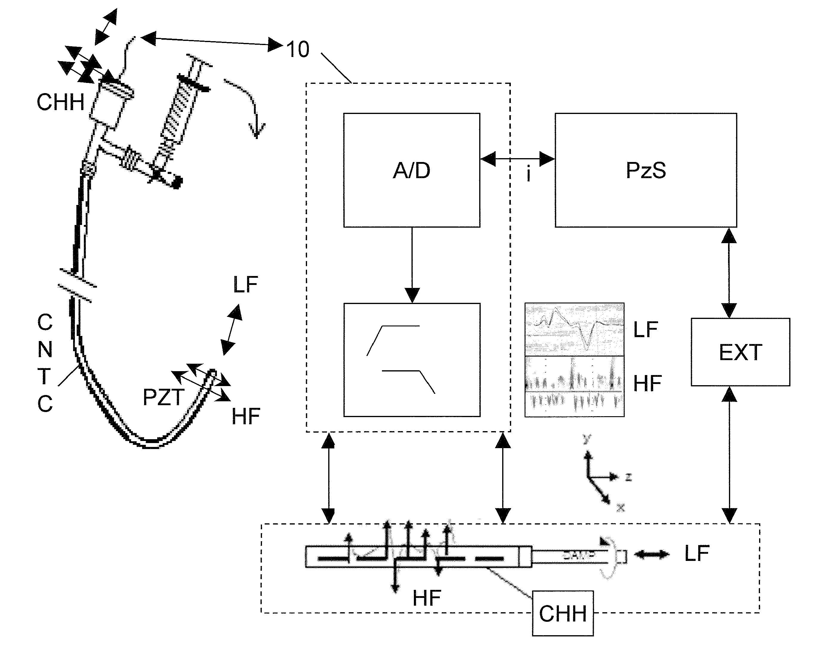
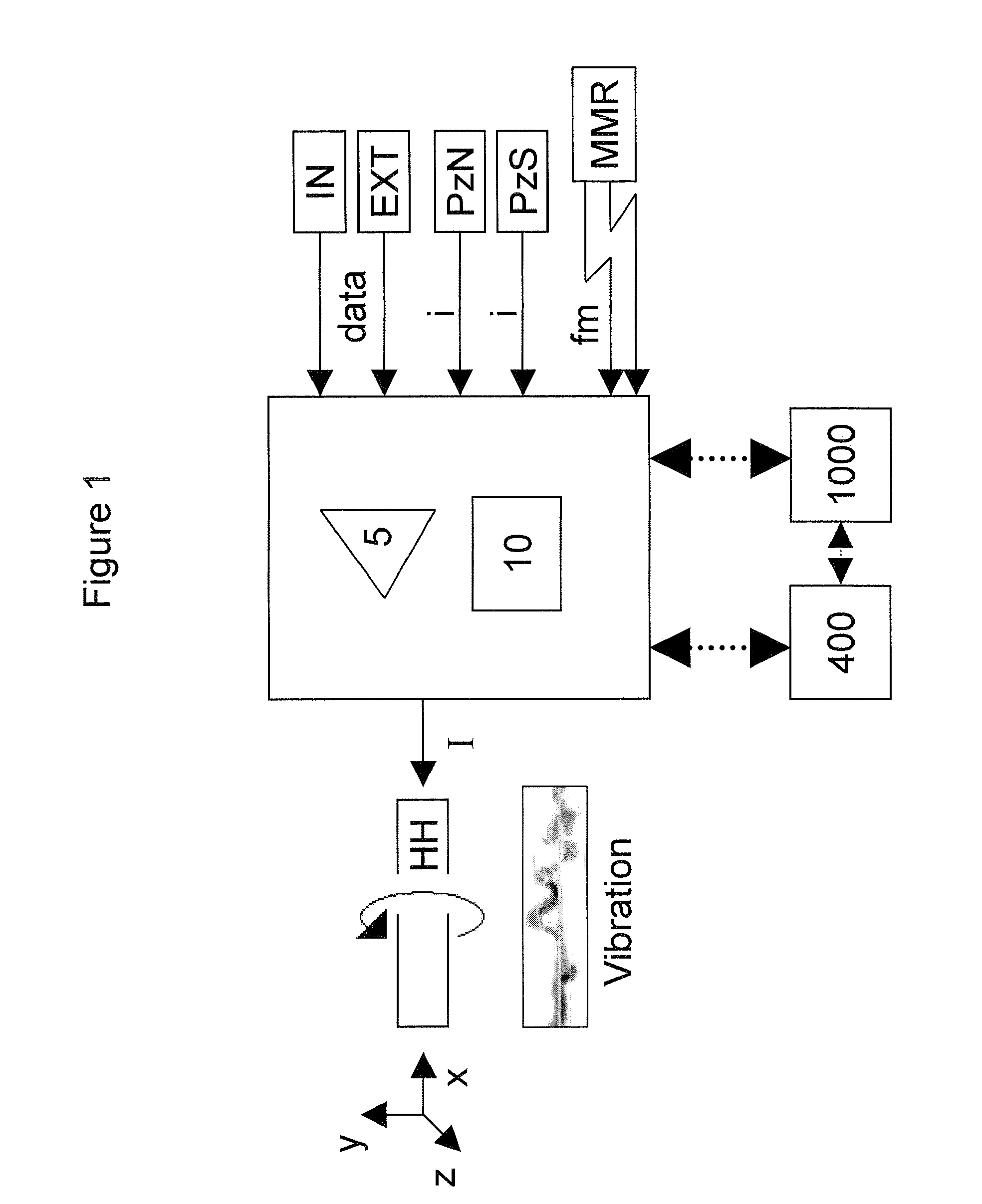
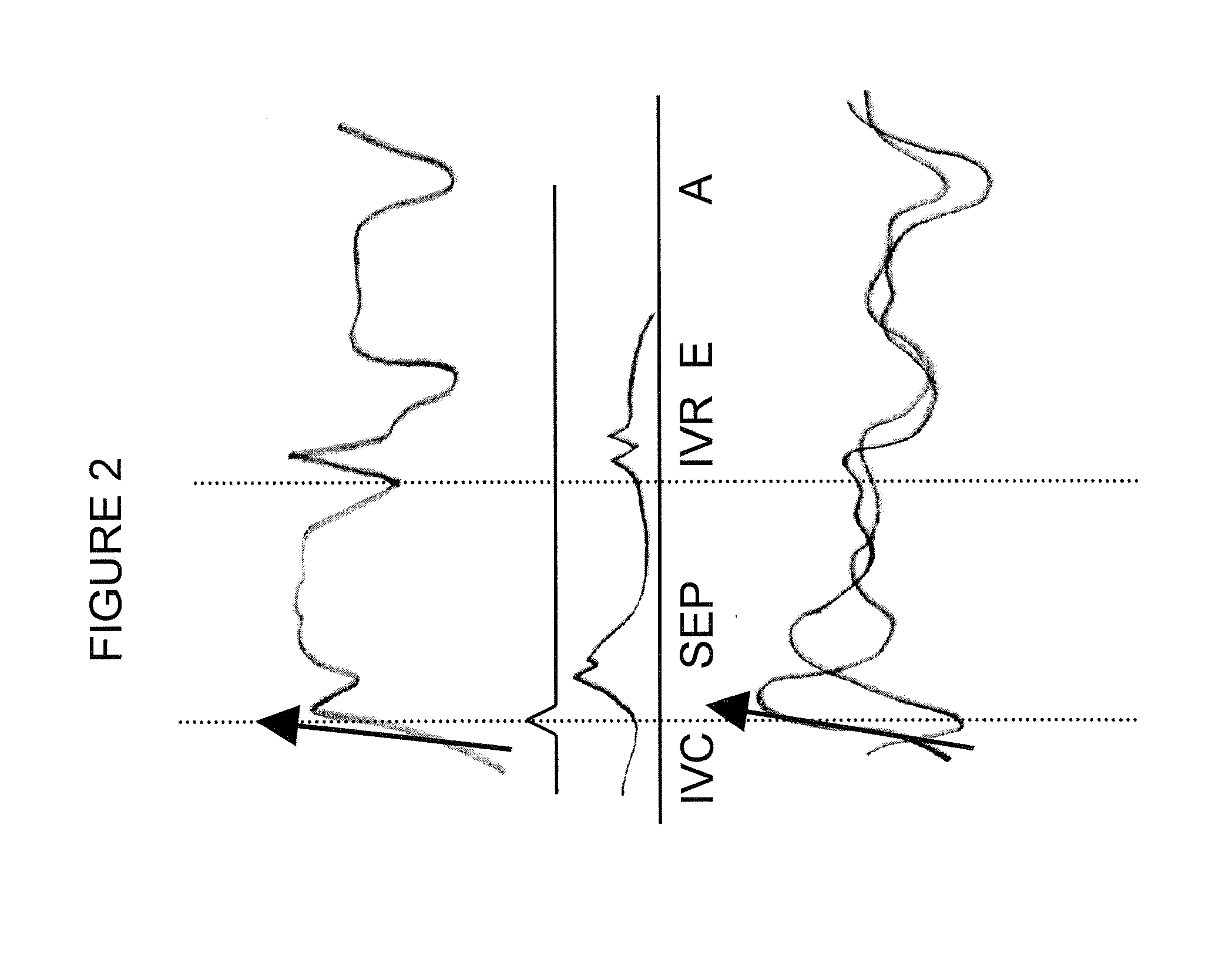
[0052]In one mode of this invention, temporary or permanently implanted cardiovascular instrumentation (e.g. cardiac catheters or implanted pacemaker / defibrillator leads, respectively) is equipped with transducers that acquire sensor signals from within the cardiac tissues and surrounding vasculature. By way of example, a piezoelectric sensor acquires information related to the motion of the contacted cardiac tissues and flow characteristics of intra-cardiac blood (e.g. turbulence, laminarity). The motion and / or deformation of the sensor are directly proportionate to that of the neighboring tissues or fluid flow. The amount of piezoelectric voltage generated will bear a relationship (i.e. linear, exponential) to sensor motion / deformation. Physiologic indices that can be derived from these measurements include but are not limited degree of displacement, torque, frequency of motion (can be along specific vectors), anatomic localization, sensor orientati...


PUM


Abstract

Cardiac tissue motion characteristics acquired by novel cardiac sensors are analyzed and processed for the derivation of physiological indices. The indices are output to a hand held local or remote volumetric haptic display and enable an operator to obtain motion related dynamic characteristics of cardiac tissues. The ability to tactually sense the motion of cardiac tissue and the affect on such motion from inserted cardiovascular instrumentation enhances the operator's performance of procedures including the positioning and placement of implanted catheters / sensors, extraction of permanently implanted leads and delivery of cardiovascular therapies. Optimal haptic rendering is achieved by using computational techniques to reconstruct the physically and perceptually relevant aspects of acquired signals and bridge the gap between the inserted catheter and operator's hand / catheter handle.

Description

RELATED APPLICATIONS[0001]I. This application is a continuation of U.S. patent application Ser. No. 12 / 836,636, filed Jul. 15, 2010 now abandoned, published as US2010 / 0312129A1, which is a continuation-in-part of U.S. patent application Ser. No. 11 / 686,602, filed Mar. 15, 2007 now U.S. Pat. No. 7,963,925, which is a continuation of U.S. patent application Ser. No. 11 / 584,465, filed Oct. 20, 2006 now abandoned, which is a continuation-in-part of U.S. patent application Ser. No. 11 / 334,935, filed Jan. 19, 2006 now abandoned, published as US2006 / 0167529A1, which claims the benefit of U.S. Provisional Application No. 60 / 660,101 filed Mar. 9, 2005 and U.S. Provisional Application 60 / 647,102 filed Jan. 26, 2005, and[0002]II. this application is a continuation of U.S. patent application Ser. No. 12 / 836,636, filed Jul. 15, 2010 now abandoned, published as US2010 / 0312129A1, in which:[0003](a) U.S. patent application Ser. No. 12 / 836,636 is also a continuation-in-part of U.S. patent applicatio...

Claims


Application Information

Patent Timeline
Patent Type & Authority Patents(United States)
IPC IPC(8): A61B5/02
CPCA61B5/1102A61B5/0031A61B5/029A61B8/08A61B5/7455
Inventor SCHECTER, STUART, O.
Owner STUART SCHECTER LLC
Learn More