
Circuits and methods for clock generation using a flying-adder divider inside and optionally outside a phase locked loop

a technology of phase locking loop and adder divider, which is applied in the direction of electrical equipment, pulse automatic control, etc., can solve the problems of reducing the bandwidth of the loop, and the price of fractional spurs for improving frequency resolution, so as to improve the resolution of the phase locking loop, the resolution is small, and the resolution is fin

Active Publication Date: 2014-03-04
XIU LIMING
View PDF18 Cites 16 Cited by
  • Summary
  • Abstract
  • Description
  • Claims
  • Application Information

AI Technical Summary

Benefits of technology

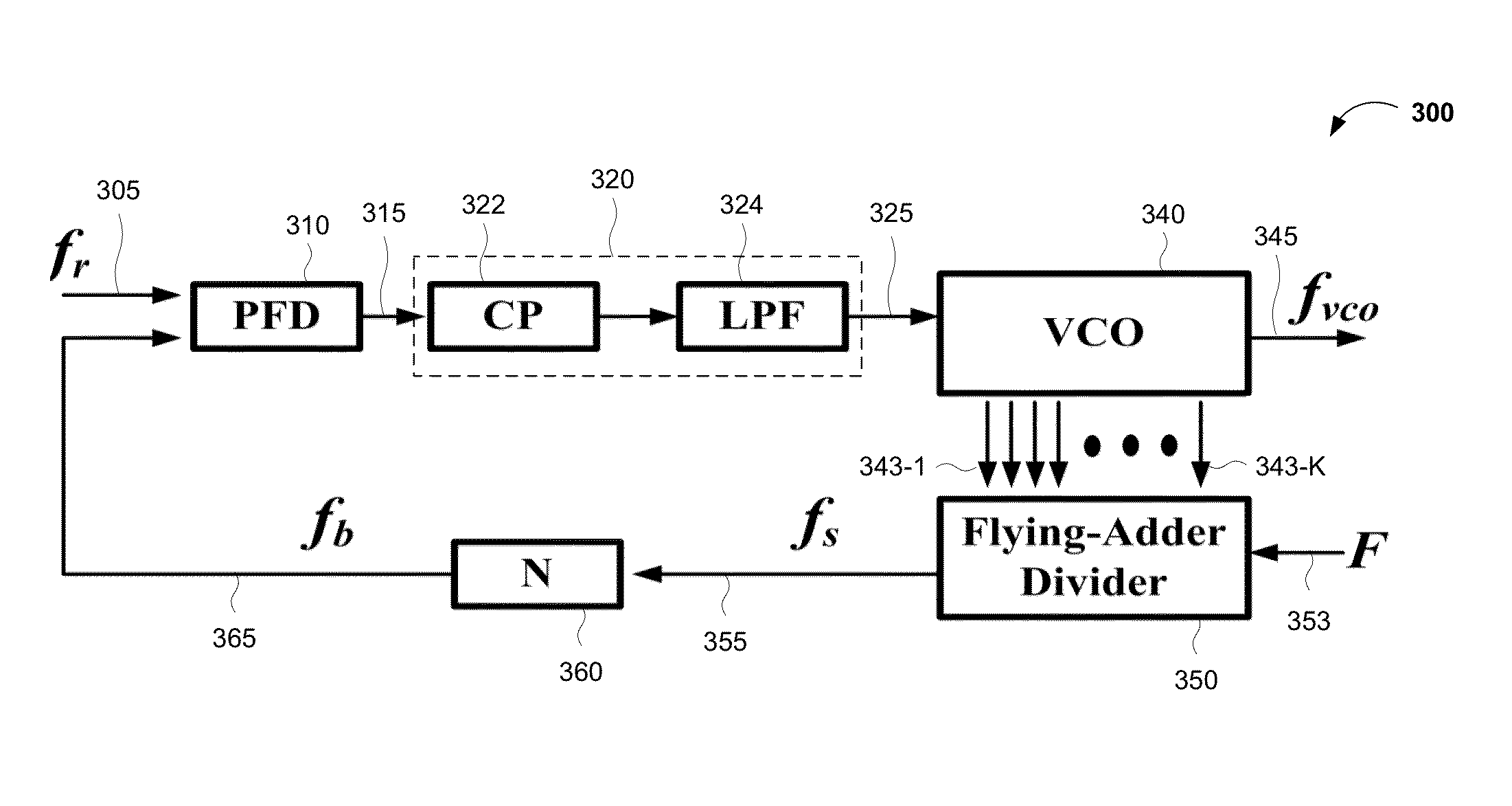
The present invention improves the resolution of a phase locked loop (PLL) without affecting the loop bandwidth or causing fractional spurs at the output. It solves the issue of using a smaller resolution to achieve finer resolution without impacting the loop bandwidth. The invention uses a flying-adder frequency synthesizer as a fractional divider and places it inside the PLL loop, improving the performance, reliability, stability, and effectiveness of electronic systems that use the invention.

Problems solved by technology

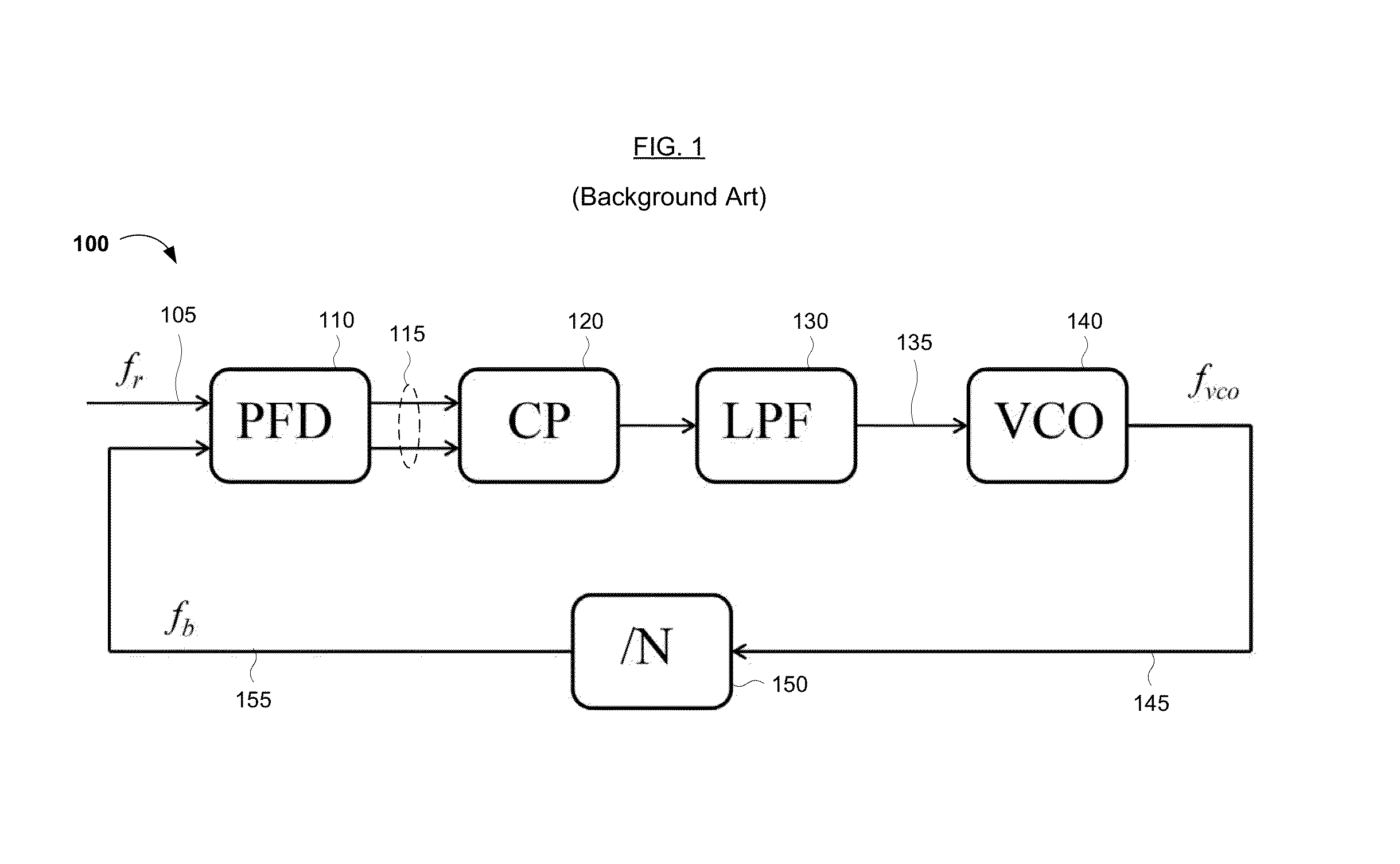
However, using a relatively small fr forces the loop bandwidth to be reduced.
Unfortunately, fractional spurs are a price that one pays for improved frequency resolution.

Method used


Image

  • Circuits and methods for clock generation using a flying-adder divider inside and optionally outside a phase locked loop
  • Circuits and methods for clock generation using a flying-adder divider inside and optionally outside a phase locked loop
  • Circuits and methods for clock generation using a flying-adder divider inside and optionally outside a phase locked loop

Examples


Embodiment Construction

[0030]Reference will now be made in detail to various embodiments of the invention, examples of which are illustrated in the accompanying drawings. While the invention will be described in conjunction with the following embodiments, it will be understood that they are not intended to limit the invention to these embodiments. On the contrary, the invention is intended to cover alternatives, modifications and equivalents, which may be included within the spirit and scope of the invention as defined by the appended claims. Furthermore, in the following detailed description, numerous specific details are set forth in order to provide a thorough understanding of the present invention. However, it will be readily apparent to one skilled in the art that the present invention may be practiced without these specific details. In other instances, well-known methods, procedures, components, and circuits have not been described in detail so as not to unnecessarily obscure aspects of the present ...


PUM


Abstract

A phase locked loop including a flying-adder divider circuit configured to receive phases of a periodic signal from a frequency generator and output a feedback signal to a phase detector, and a method of generating a periodic signal using such a flying-adder circuit, are disclosed. The flying-adder divider circuit generally includes a flying-adder and one or two divide-by-N dividers. The flying-adder receives K phases of the periodic signal, where K is an integer of at least 2, and generates a divided periodic signal from the K phases. The phase locked loop may include flying-adder divider circuits inside and / or outside the loop.

Description

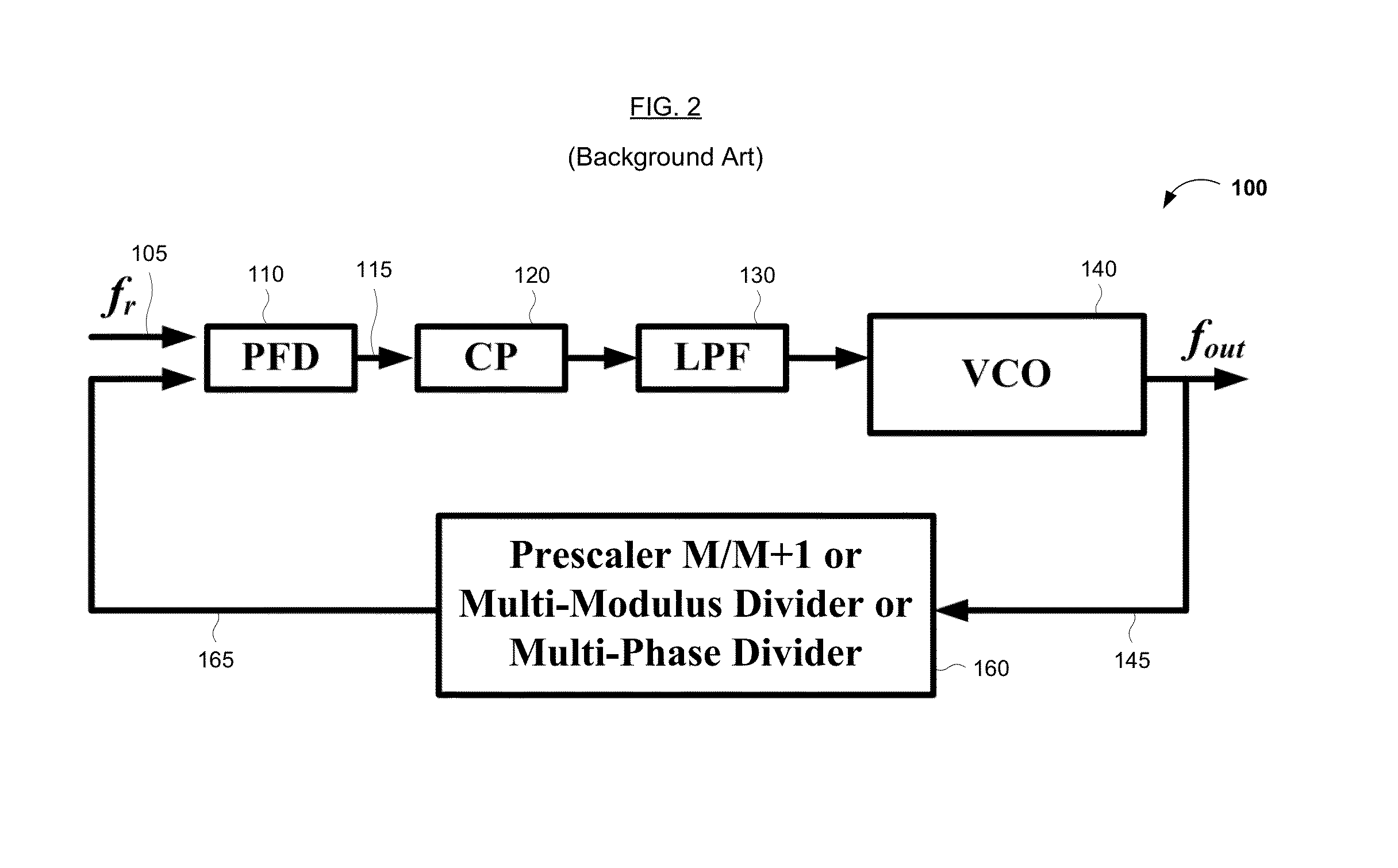
FIELD OF THE INVENTION[0001]The present invention generally relates to the field of clock generation. More specifically, embodiments of the present invention pertain to circuitry and methods for clock generation using a flying-adder divider in a phase locked loop. The present circuitry and methods improve frequency resolution of an integer-N PLL without decreasing its bandwidth.DISCUSSION OF THE BACKGROUND[0002]Referring to FIG. 1, an integer-N phase locked loop (PLL) 100 typically is locked when the frequency (fb) of its feedback signal 155 is equal to the frequency (fr) of an incoming clock signal 105. Therefore, the frequency (fvco) of the voltage controlled oscillator (VCO) 140 in the loop 100 equals N*fr, where N is the divide-by ratio of a / N divider 150, the frequency resolution at the VCO 140 is fr, and the bandwidth of the PLL loop is usually designed less than fr / 10. To improve frequency resolution, a relatively small frequency (fr) of the incoming clock signal 105 is used...

Claims


Application Information

Patent Timeline
Patent Type & Authority Patents(United States)
IPC IPC(8): H03L7/06
CPCH03L7/1806H03L7/081H03L7/197
Inventor XIU, LIMING
Owner XIU LIMING
Learn More