Plasma processing device and method of monitoring plasma discharge state in plasma processing device

a plasma processing device and plasma technology, applied in the direction of fluid pressure measurement, instruments, vacuum gauges, etc., can solve the problems of low detection accuracy, difficult to accurately detect the state of plasma discharge, and disadvantageous methods

Active Publication Date: 2014-03-11
PANASONIC CORP
View PDF12 Cites 95 Cited by
  • Summary
  • Abstract
  • Description
  • Claims
  • Application Information

AI Technical Summary

Problems solved by technology

However, these methods are disadvantageous as follows.
In the case where it is necessary to generate plasma discharge under the condition of low output, the detection accuracy is low and it is difficult to accurately detect a state of plasma discharge.

Method used


Image

  • Plasma processing device and method of monitoring plasma discharge state in plasma processing device
  • Plasma processing device and method of monitoring plasma discharge state in plasma processing device
  • Plasma processing device and method of monitoring plasma discharge state in plasma processing device

Examples


embodiment 1

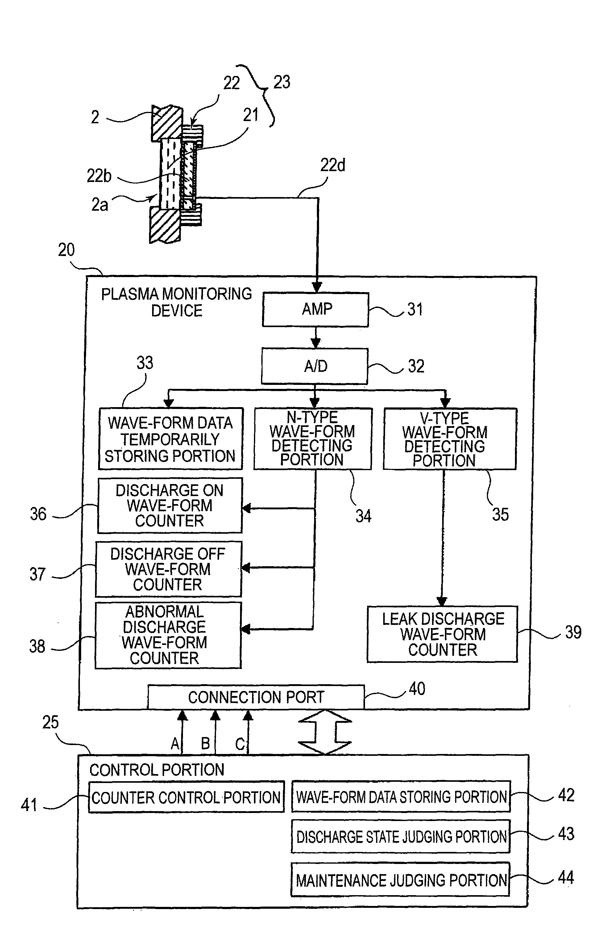
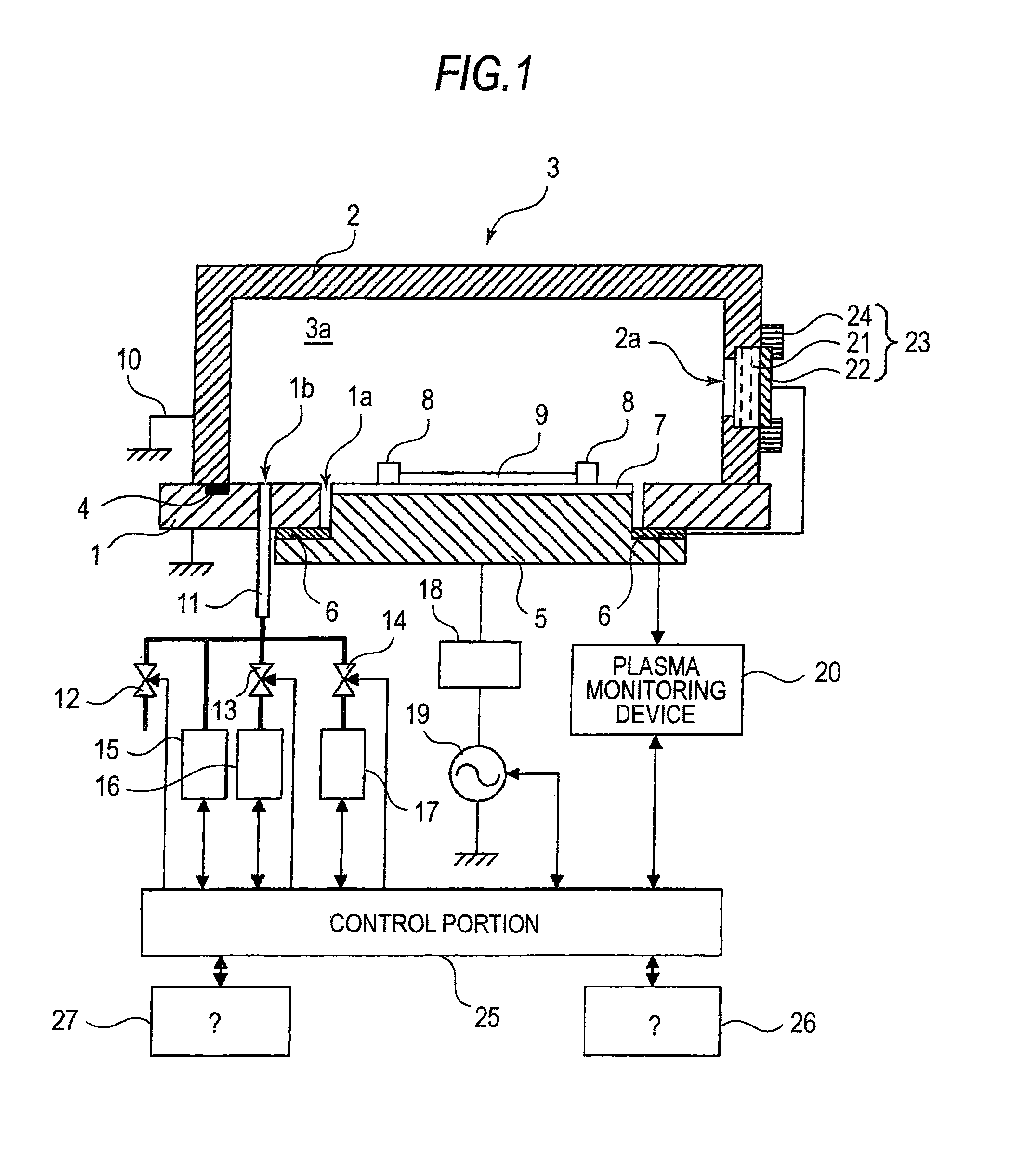
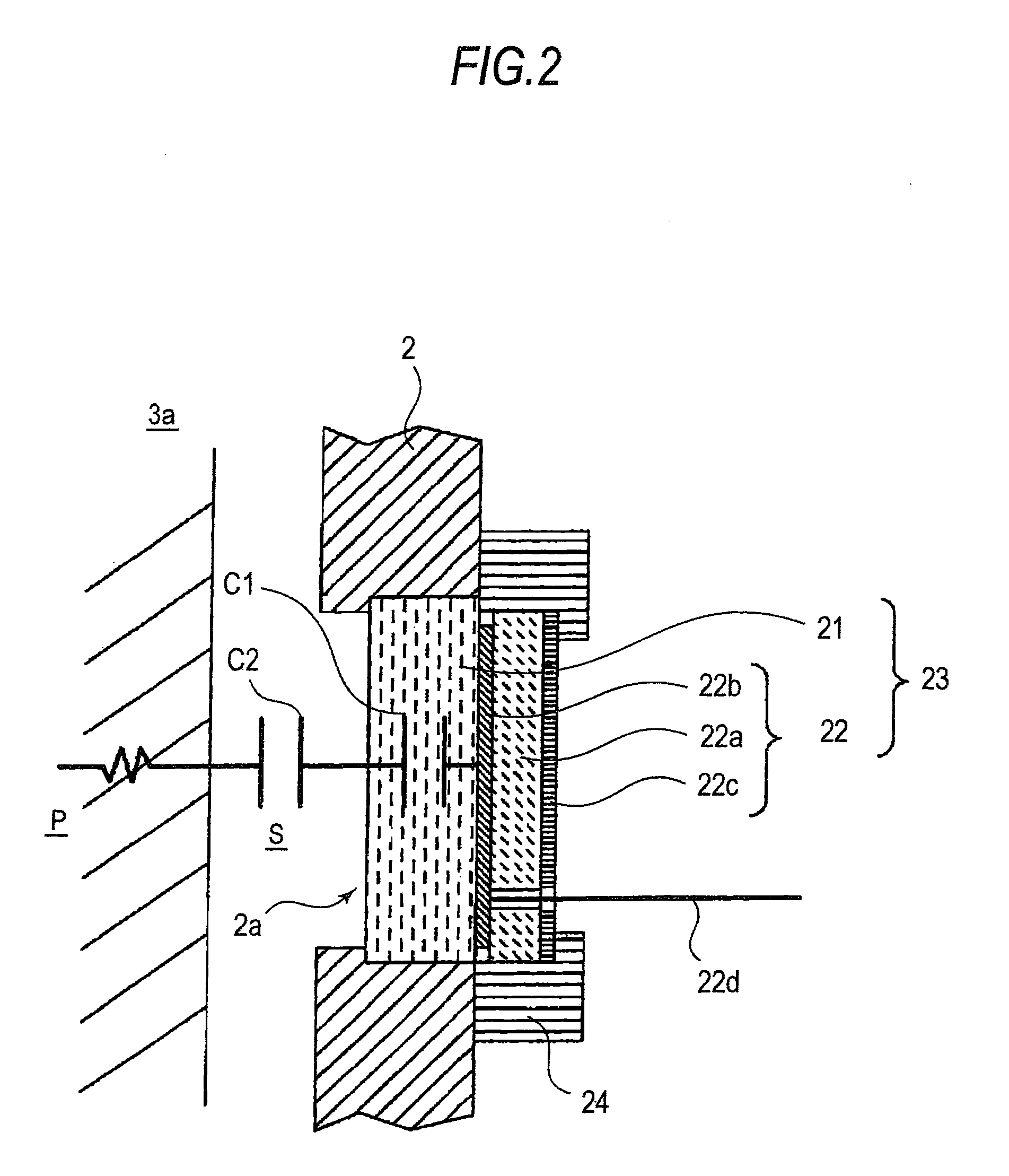
[0021]FIG. 1 is a sectional view showing a plasma processing device of Embodiment 1 of the present invention. FIG. 2 is a schematic illustration for explaining an arrangement of the discharge detection sensor used for the plasma processing device of Embodiment 1 of the present invention. FIG. 3 is a block diagram showing an arrangement of the plasma discharge state monitoring device of the plasma processing device of Embodiment 1 of the present invention. FIGS. 4A and 4B are schematic illustrations for explaining an electric potential change wave-form and a wave-form monitoring time zone in the plasma discharge state monitoring method of Embodiment 1 of the present invention. FIG. 5 is a flow chart of the discharge state judgment processing executed in the plasma discharge state monitoring method of Embodiment 1 of the present invention.FIG. 6 is a flow chart of the maintenance judgment processing executed in the plasma discharge state monitoring method of Embodiment 1 of the presen...

embodiment 2

[0063]FIG. 7 is a block diagram showing a constitution of the plasma discharge state monitoring device in the plasma processing device of Embodiment 2 of the present invention. FIGS. 8A and 8B are schematic illustrations for explaining an electric potential change wave-form and a wave-form monitoring time zone in the plasma discharge state monitoring method of Embodiment 2 of the present invention. FIG. 9 is a flow chart showing an electric discharge state judgment processing in the plasma discharge state monitoring method of Embodiment 2 of the present invention.

[0064]In the present Embodiment 2, a function of the N-type wave-form detecting portion 34 in Embodiment 1 is divided into two N-type wave-form detecting portions according to a wave form pattern of an object to be detected, wherein one is an N1-type wave-form detecting portion 34A and the other is an N2-type wave-form detecting portion 34B. The N1-type wave-form detecting portion 34A chiefly detects a wave-form pattern of ...


PUM

PropertyMeasurementUnit
plasma discharge stateaaaaaaaaaa
frequencyaaaaaaaaaa
impedanceaaaaaaaaaa

Abstract

An object is to provide a plasma processing device capable of rightly monitoring existence of plasma discharge and also rightly monitoring existence of abnormal discharge. Another object of the present invention is to provide a method of monitoring a state of plasma discharge in the plasma processing device.A discharge detection sensor 23, in which a dielectric member 21 and a probe electrode unit 22 are combined with each other, is attached to an opening portion 2a provided in a lid portion 2 composing a vacuum chamber. A change in the electric potential induced in the probe electrode 22b according to a change in plasma discharge is received, electric potential change wave-forms of specific patterns are respectively detected by an N-type wave-form detecting portion 34 and V-type wave-form detecting 35, and a discharge state judgment including a judgment of whether the electric discharge exists or does not exist and whether the electric discharge is normal or abnormal is made according to a counted value of counting the number of times of appearance of these electric potential change wave forms for each type of wave-form by a discharge ON wave-form counter 36, a discharge OFF wave-form counter 37, an abnormal discharge wave-form counter 38 and a leak discharge wave-form counter 39.

Description

TECHNICAL FIELD[0001]The present invention relates to a plasma processing device for executing plasma processing for an object to be processed such as a board. The present invention also relates to a method of monitoring a plasma discharge state for monitoring whether the plasma discharge is executed or not in the plasma processing device or whether the plasma discharge is normal or abnormal.BACKGROUND ART[0002]Plasma processing is well known as a surface processing method for executing cleaning or etching upon an object to be processed such as a board on which electronic parts are mounted. In plasma processing, a board to be processed is put into a vacuum chamber forming a processing chamber. Then, plasma discharge is generated in the processing chamber. When ions and electrons generated as a result of the plasma discharge are made to act on a surface of the board, predetermined surface processing is executed. In order to stably execute the plasma processing at high quality, it is ...

Claims


Application Information

Patent Timeline
Patent Type & Authority Patents(United States)
IPC IPC(8): C23F1/00C03C25/68C03C15/00H01L21/306
CPCH01J37/32935H01J2237/0206H01J37/32091H01L21/3065H01J37/32
Inventor MIZUKAMI, TATSUHIROARITA, KIYOSHINONOMURA, MASARU
Owner PANASONIC CORP
Why Eureka
Try Eureka