
Spacing/levelling device for laying slab products for surface cladding

a technology of levelling device and laying slab, which is applied in the direction of building components, roof tools, building scaffolds, etc., can solve the problem of not being applicable at the corners of the slab products,

Active Publication Date: 2014-03-18
RAIMONDI
View PDF14 Cites 53 Cited by
  • Summary
  • Abstract
  • Description
  • Claims
  • Application Information

AI Technical Summary

Benefits of technology

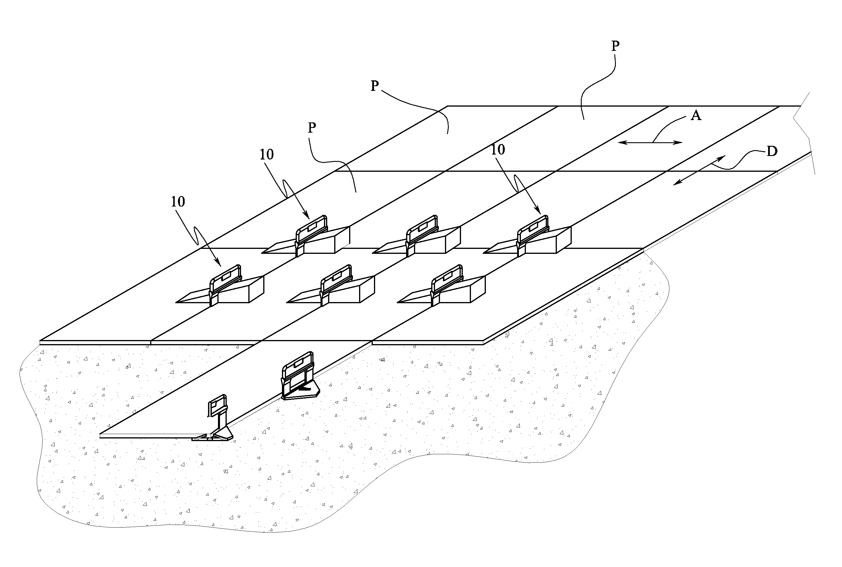
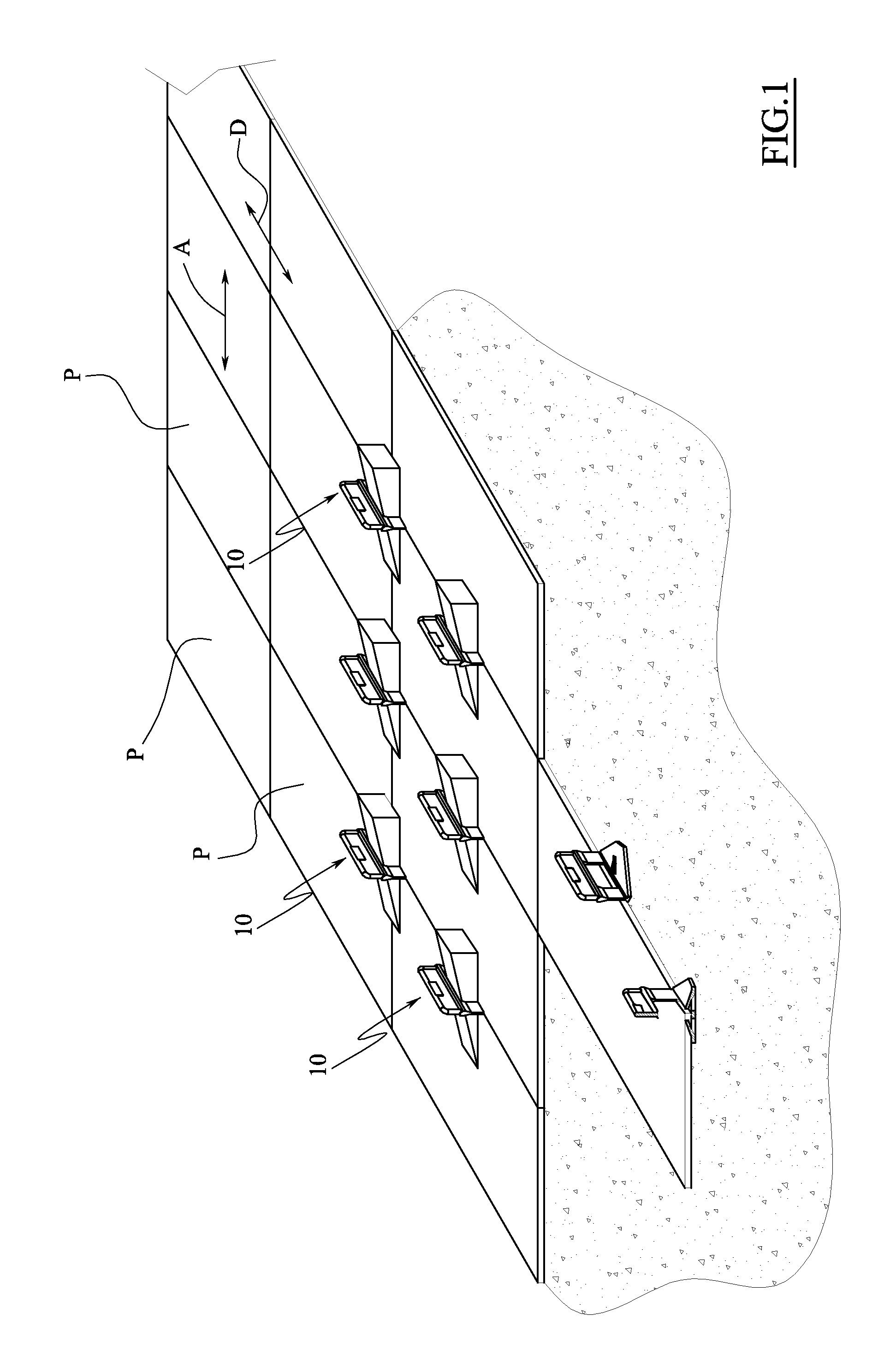
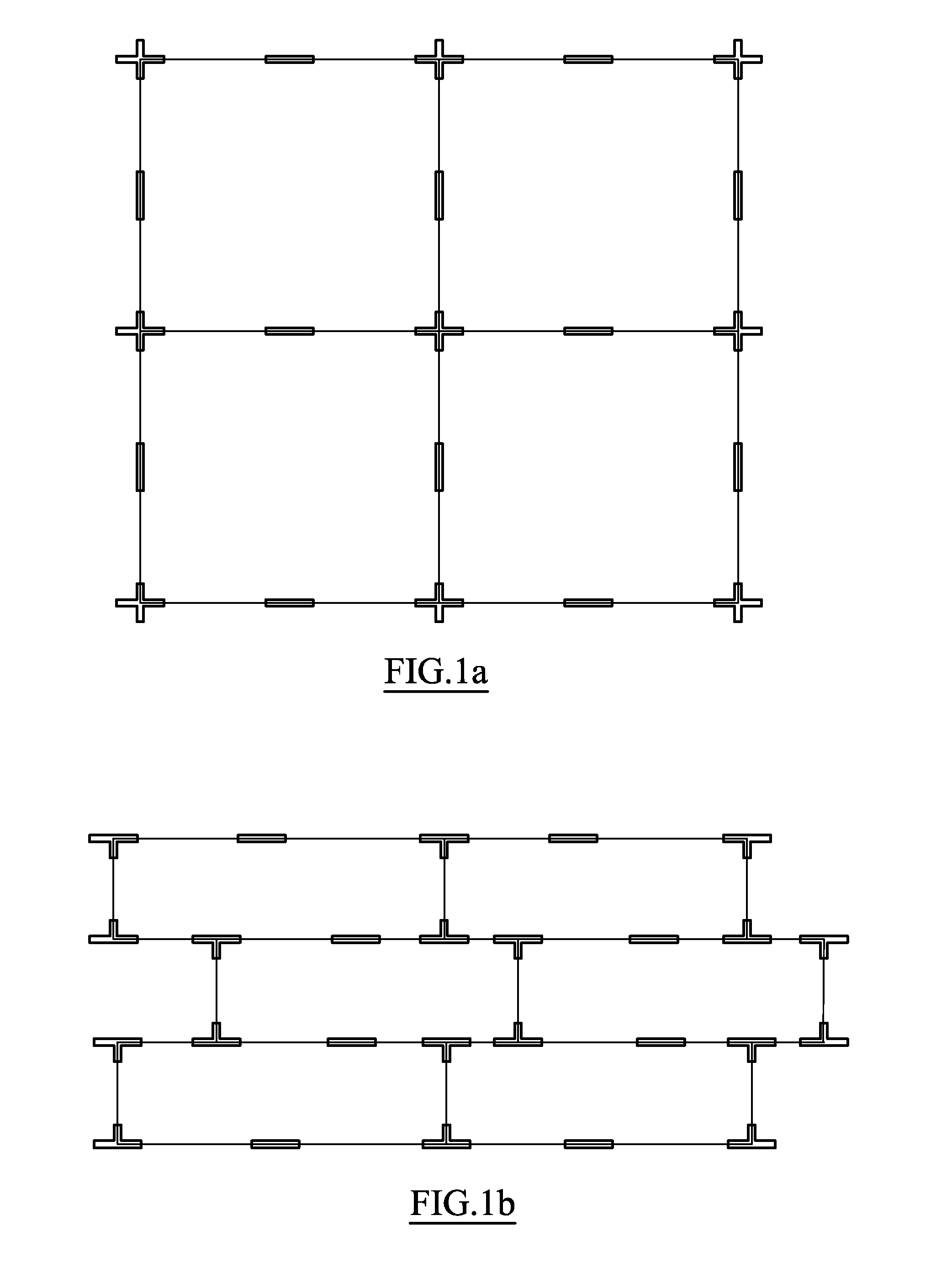
The present invention is a spacing / levelling device for laying slab-shaped products, such as tiles, for cladding surfaces. The device has a base and presser means for pressing the in-view surfaces of the products. It also includes a corner spacer that can be moved between a raised position and a non-interfering position to align the products along a perpendicular direction. The device can be used at the lateral edges of two slab products and at the corners of the products, and has both a levelling function and a distancing function between the products. The invention simplifies the process of laying slab-shaped products and reduces the need for multiple devices.

Problems solved by technology

Although these spacing / levelling devices are particularly effective in their tile-levelling action, they however have the drawback of not being applicable at the corners of the slab products, i.e. where a greater precision is necessary in the carrying-out of the alignment along the flanking direction of the products and also in the laying thereof, such as to prevent the surface from being irregular.

Method used


Image

  • Spacing/levelling device for laying slab products for surface cladding
  • Spacing/levelling device for laying slab products for surface cladding
  • Spacing/levelling device for laying slab products for surface cladding

Examples


first embodiment

[0023]FIG. 6 is a lateral view of a first variant of the spacing / levelling device according to the invention;

[0024]FIG. 7 is an axonometric view from above of FIG. 6;

[0025]FIG. 8 is a lateral view of a second variant of the first embodiment of the spacing / levelling device of the invention;

[0026]FIG. 9 is an axonometric view from above of FIG. 8;

[0027]FIG. 10 is a lateral view of a third variant of the first embodiment of the spacing / levelling device of the invention;

[0028]FIG. 11 is an axonometric view from above of FIG. 10;

second embodiment

[0029]FIG. 12 is a lateral view of the spacing / levelling device according to the invention;

[0030]FIG. 13 is an axonometric view from above of FIG. 12;

[0031]FIG. 14 is a plan view of FIG. 13.

third embodiment

[0032]FIG. 15 is an axonometric view from above of the spacing / levelling device according to the invention.

[0033]FIG. 16 is a lateral view of FIG. 15.

[0034]FIG. 17 is a frontal view of FIG. 15.

[0035]FIG. 18 is cross-section XVIII-XVIII of FIG. 17.


PUM


Abstract

An intake manifold (2) of comburent air is presented for an internal combustion engine (1) provided with a recirculating conduit (60) of exhaust gases. The intake manifold (2) includes a first inlet mouth (213) of the comburent air, a second inlet mouth (214) in communication with the recirculating conduit (60) of the exhaust gases, and a plurality of outlet mouths (201), having a wall (7) positioned in front of each of the outlet mouths (201) and configured for dividing the internal volume of the intake manifold (2) into two chambers (215, 204), the first chamber (215) being placed in communication with the first inlet mouth (213) and the second inlet mouth (214) and the second chamber (204) being placed in communication with the outlet mouths (201), the wall (7) defining an opening (70) adapted for placing the first chamber (215) and the second chamber (204) in communication.

Description

TECHNICAL FIELD[0001]The present invention relates to a spacing / levelling device for laying slab-shaped products, such as tiles and the like, for cladding surfaces.PRIOR ART[0002]In the sector of laying tiles for cladding surfaces, such as floorings, walls and the like, the use of spacer devices is known, which, as well as spacing the tiles, enable them also to be laid in planar fashion. These devices are commonly known as spacing / levelling devices.[0003]Spacing / levelling devices of known type generally comprise a base, positionable below the laying surface of at least two adjacent tiles, from which at least a separator element projects which is destined to contact, with its lateral flanks, the facing sides of the two tiles to be arranged adjacent on the laying surface.[0004]The spacing / levelling device is also provided with presser means which press the in-view surfaces of the products towards the base in such a way as to level them, cooperating with the portion of the separator el...

Claims


Application Information

Patent Timeline
Patent Type & Authority Patents(United States)
IPC IPC(8): E04B9/00E04B2/82E04G1/22
CPCE04F15/02005E04F21/0092E04F15/02022
Inventor SIGHINOLFI, GIORGIO
Owner RAIMONDI
Learn More