Crankcase ventilation and vacuum generation

Inactive Publication Date: 2013-12-26
FORD GLOBAL TECH LLC
View PDF9 Cites 84 Cited by
  • Summary
  • Abstract
  • Description
  • Claims
  • Application Information

AI Technical Summary

Benefits of technology

[0007]In this way, by enabling flow of intake air and/or crankcase gases through a venturi/aspirator/ejector irrespective of the direction of flow through a PCV line, flow during both boosted and un-boosted engine conditions can be advantageously used to generate vacuum. In other words, a much broader window for vacuum generation is enabled, and engine vacuum generation efficiency is improved. By enabling vacuum generation to be enabled

Problems solved by technology

However the inventors herein have identified potential issues with such an approach.
As another example, the air flow rate through the ejector required to generate sufficient vacuum flow rate may interfere with the minimum controllable air flow budget due to more air flowing than the eng

Method used


Image

  • Crankcase ventilation and vacuum generation
  • Crankcase ventilation and vacuum generation
  • Crankcase ventilation and vacuum generation

Examples


Embodiment Construction

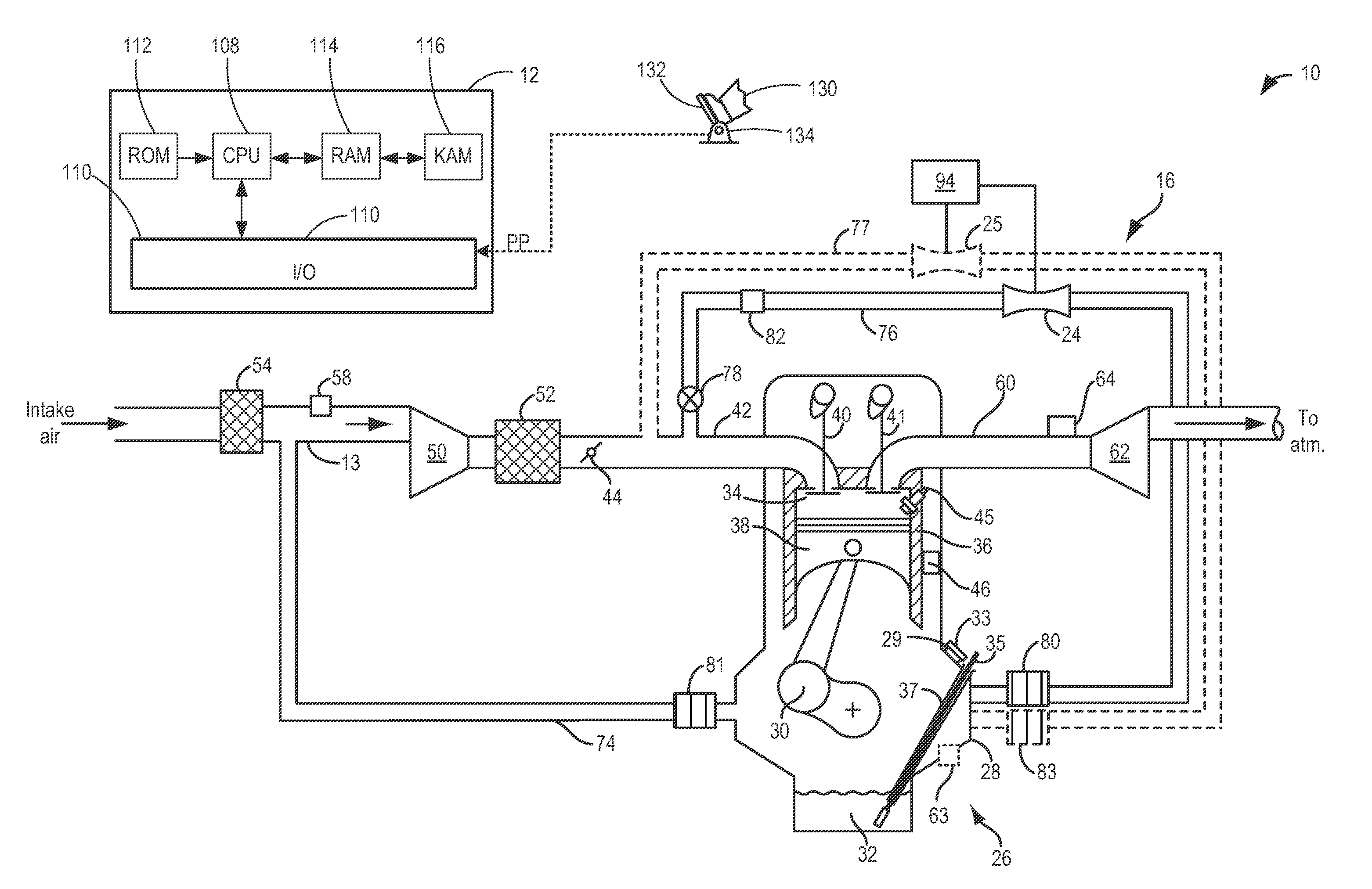
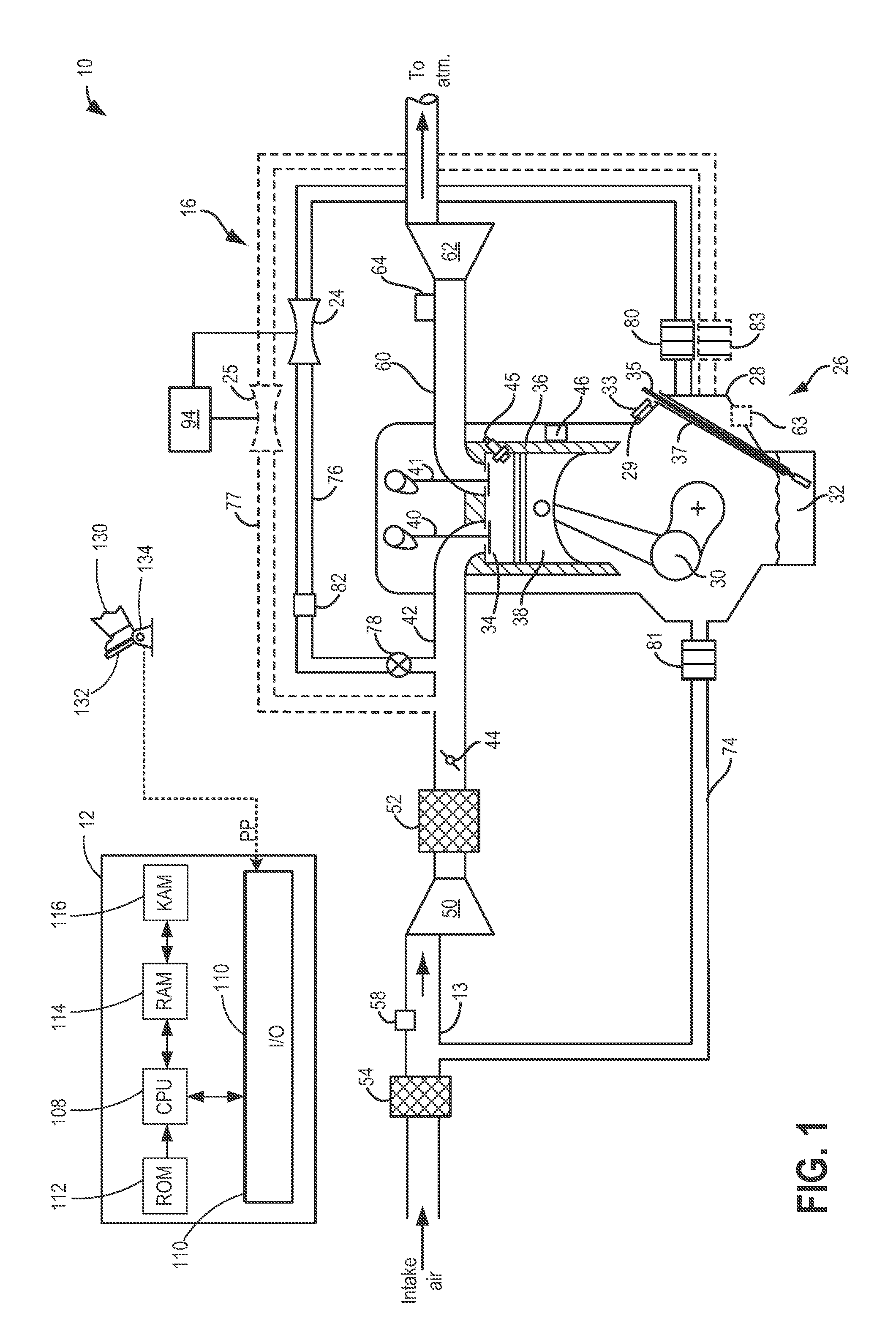
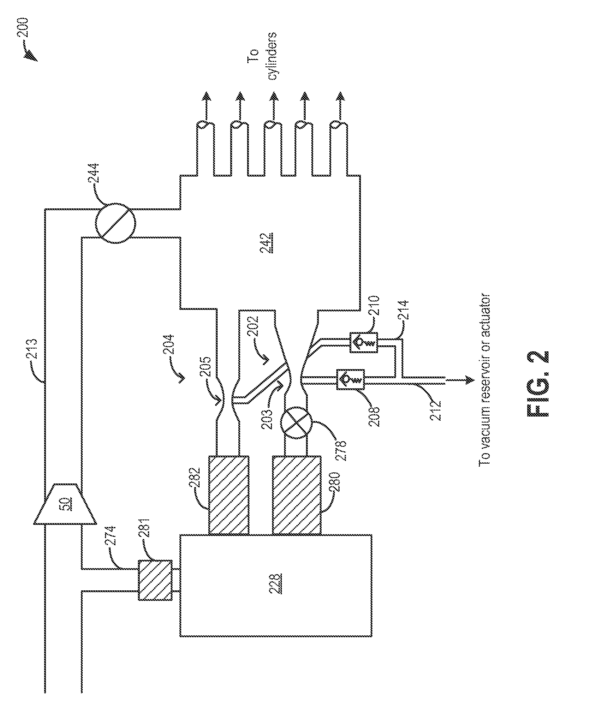
[0014]The following description relates to systems and methods for flowing air and / or crankcase gases in a positive crankcase ventilation (PCV) line of an engine system (such as the engine system of FIG. 1) through an aspirator to generate vacuum. Based on a direction of flow in the PCV line between an engine intake manifold and a crankcase, and further based on the configuration of the aspirators (such as the aspirators of FIGS. 2-3), the flow may be directed through a selected aspirator. An engine controller may be configured to perform control routines, such as those of FIGS. 4-6, to direct flow through the selected aspirator(s) and store the generated vacuum in a vacuum reservoir for subsequent use. In this way, vacuum may be generated irrespective of the direction of flow (of air or crankcase gases) in the PCV line. Additionally, vacuum generation may be enabled for a wider range of engine operating conditions.

[0015]Referring now to FIG. 1, it shows an example system configurat...


PUM


Abstract

Methods and systems are provided for generating vacuum from crankcase ventilation flow. During both directions of gas flow between an engine intake manifold and a crankcase, gases are directed through one or more aspirators to produce vacuum. The drawn vacuum may then be used to operate various engine vacuum actuators.

Description

TECHNICAL FIELD[0001]This application relates to using crankcase ventilation for vacuum generation during boosted and un-boosted engine operation via the use of a variable venturi.BACKGROUND AND SUMMARY[0002]Vehicles may include various actuators that operate using a source of vacuum. The vacuum actuators may be used for actuation, enabling vehicle brakes, purging a fuel canister, improving an engine start, performing a leak test, etc. Accordingly, various vacuum sources may be available on the vehicle. These may include dedicated vacuum pumps as well as vacuum generating ejectors, aspirators, and venturis. Engine control systems may harness an air flow through the ejector / aspirator / venturi to produce a vacuum which is then used for the various actuators.[0003]One example approach for directing a flow through an ejector to generate vacuum is shown by Suzuki et al. in US2008 / 0103667. Therein, an air ejector is coupled in a surge tank upstream of a branched intake manifold having air ...

Claims


Application Information

Patent Timeline
IPC IPC(8): F01M13/04F01M13/00
CPCF01M13/023F02B37/00F02M25/06F02M35/10222F02M35/10229Y02T10/12
Inventor PURSIFULL, ROSS DYKSTRACRISP, NICHOLAS DASHWOODULREY, JOSEPH NORMAN
Owner FORD GLOBAL TECH LLC
Why Eureka
Try Eureka