Method and system for vacuum generation using a throttle

a technology of vacuum generation and throttle, which is applied in the direction of electric control, combustion air/fuel air treatment, machines/engines, etc., can solve the problems of limited increased related expenses, and additional expenses, so as to improve the vacuum generation potential of the throttle plate, improve the control of airflow into the intake manifold, and improve the effect of airflow compensation

Inactive Publication Date: 2018-09-25
FORD GLOBAL TECH LLC
View PDF8 Cites 2 Cited by
  • Summary
  • Abstract
  • Description
  • Claims
  • Application Information

AI Technical Summary

Benefits of technology

[0006]The inventors herein have identified an approach to at least partly address the above issues. In one example approach, a method is provided for an engine including a hollow intake throttle plate having a perforated edge. The method comprises adjusting a position of the hollow throttle plate with the perforated edge and generating vacuum via intake airflow past the perforated edge of the hollow throttle plate. The generated vacuum is then applied to a vacuum consumption device fluidly coupled to the hollow throttle plate via a hollow shaft. In this way, the throttle plate can function as an aspirator and supply vacuum to the vacuum consumption device.
[0008]In this way, a venturi flow passage created at the boundary of the hollow throttle plate in a more closed position can be advantageously used to generate vacuum for a vacuum consumption device. Perforations at the periphery of the throttle plate can be used to provide a channel to draw air or gas from the vacuum consumption device via the hollow shaft. By adjusting the location and size of perforations along the throttle periphery, vacuum can be generated over a larger portion of the throttle's periphery, such as over the entire periphery. As such, this improves the vacuum generation potential of the throttle plate. In addition, airflow into the intake manifold can be better controlled by adjusting the distance between the inside of the intake passage and the edge of the throttle plate. Furthermore, since air received from the vacuum consumption device during vacuum application is received substantially at the throttle plate, airflow errors can be better compensated for. By combining the functions of a throttle and an aspirator into a single hollow throttle plate with a perforated edge and a hollow shaft, additional control valves, such as an ASOV, and parts may not be needed. Further, the vacuum generation ability of the throttle is improved without requiring significant modifications to the intake passage. By reducing the number and size of components required for vacuum generation, manufacturing expenses may be lowered and packaging issues may be averted.

Problems solved by technology

As an example, the vacuum generation potential of the throttle is limited.
However, fabricating these control bores may result in significant modifications to the design of the intake passage which can increase related expenses.
In the approaches that use one or more aspirators to generate vacuum, additional expenses may be incurred because of individual parts that form the aspirator including nozzles, mixing and diffusion sections, and check valves.
Further, at idle or low load conditions, it may be difficult to control the total air flow rate into the intake manifold since the flow rate is a combination of leakage flow from the throttle and airflow from the aspirator.
Typically, an aspirator shut off valve (ASOV) may be included along with the aspirator to control airflow but with added cost.
Further, installing aspirators in the intake can lead to constraints on space availability as well as packaging issues.

Method used


Image

  • Method and system for vacuum generation using a throttle
  • Method and system for vacuum generation using a throttle
  • Method and system for vacuum generation using a throttle

Examples


Embodiment Construction

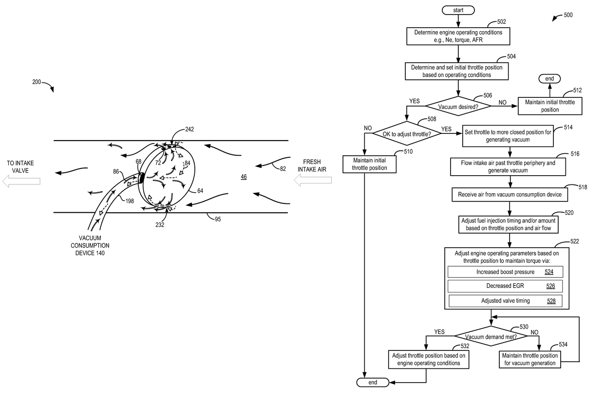
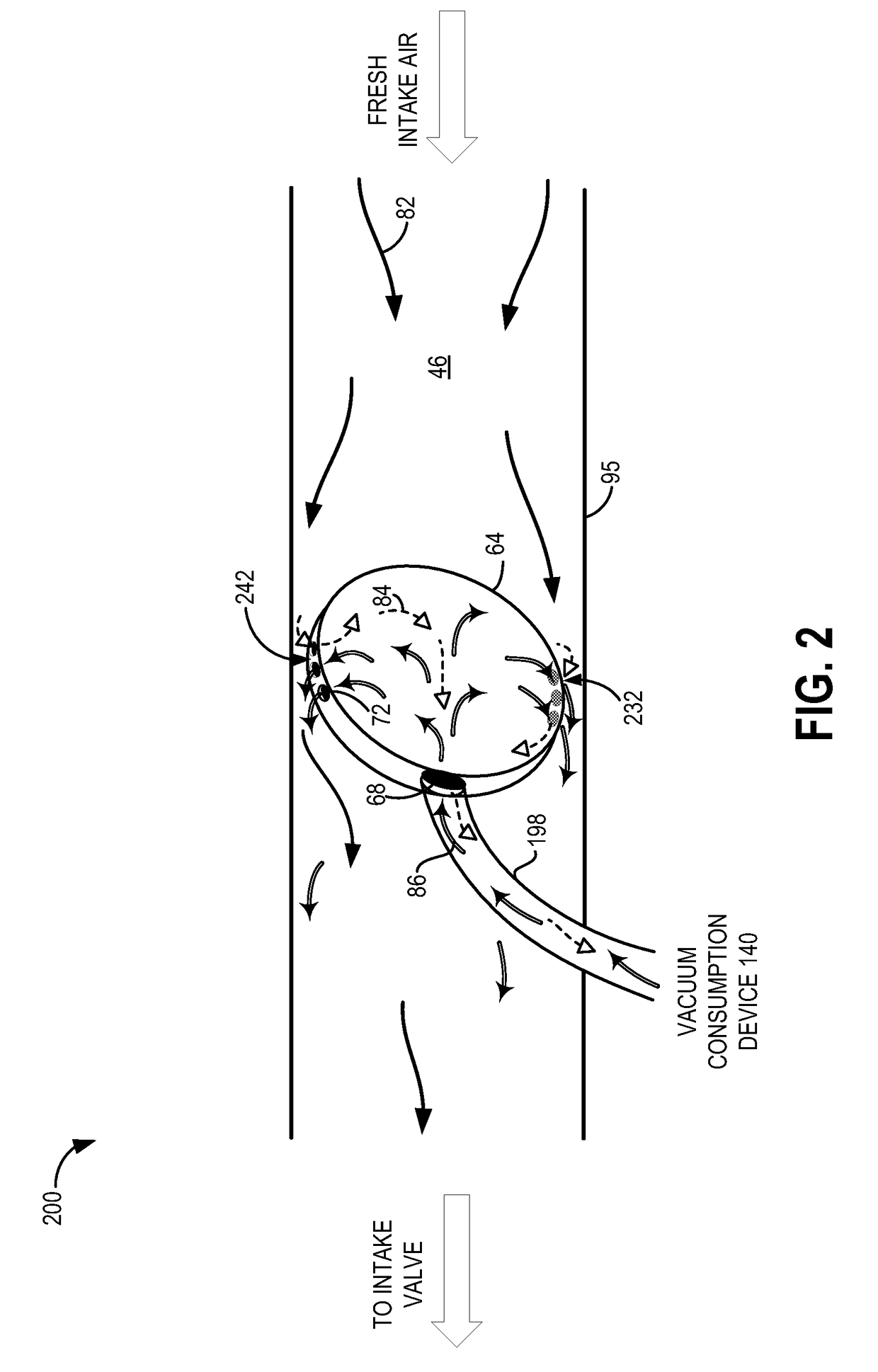
[0016]Methods and systems are described for generating vacuum within an intake passage in an engine, such as the engine system shown in FIG. 1. The intake passage may be provided with an intake throttle comprising a hollow throttle plate with a perforated edge coupled to a vacuum consumption device via a hollow shaft, as shown in FIGS. 2-4. A controller may be configured to perform a routine to modify a throttle position based on vacuum demand from the vacuum consumption device (FIG. 5). Various operating parameters may be adjusted (FIG. 6), as throttle position is varied, to maintain engine torque.

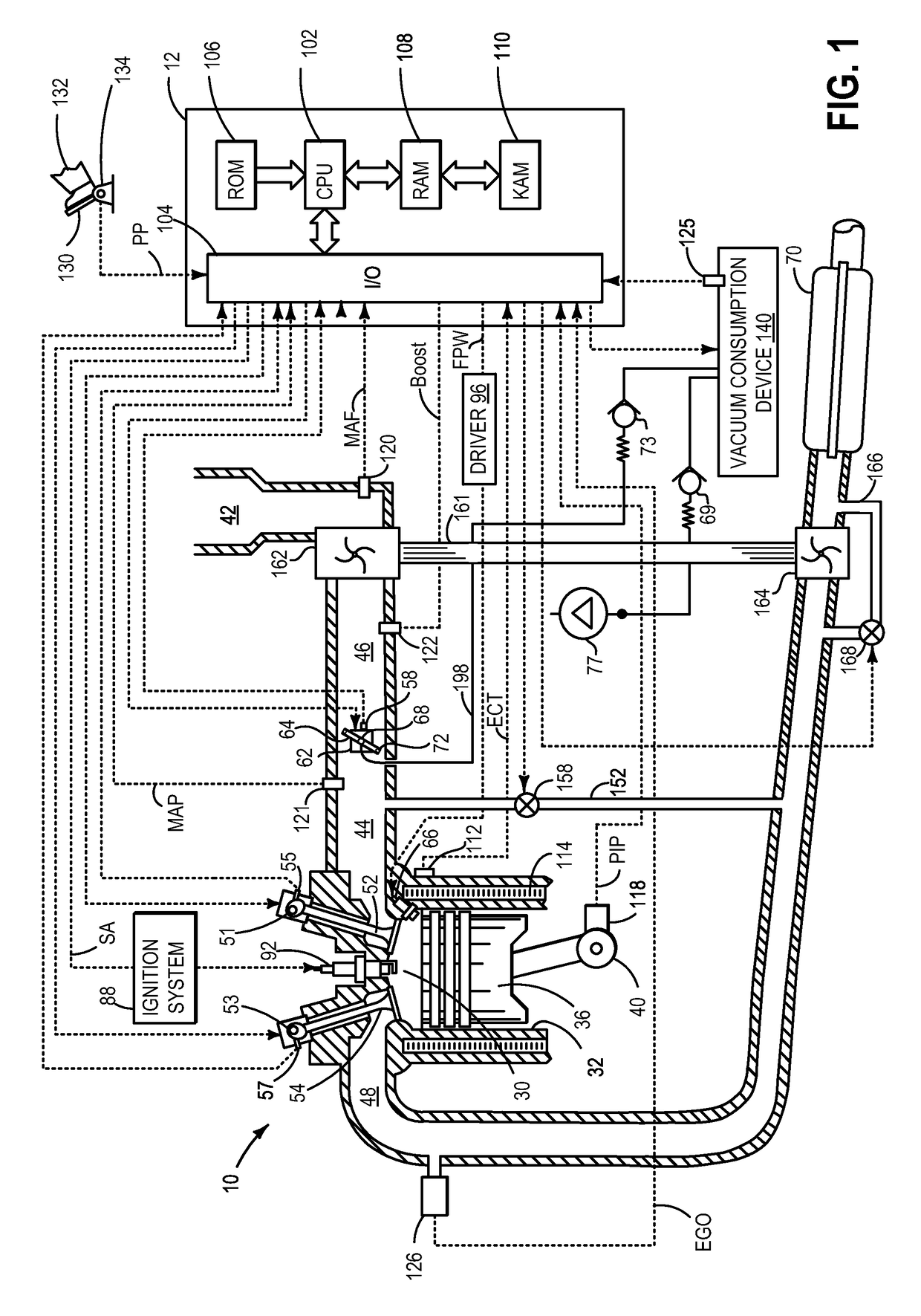
[0017]Referring now to FIG. 1, it shows a schematic depiction of a spark ignition internal combustion engine 10. Engine 10 may be controlled at least partially by a control system including controller 12 and by input from a vehicle operator 132 via an input device 130. In this example, input device 130 includes an accelerator pedal and a pedal position sensor 134 for generating a proporti...


PUM


Abstract

Various systems and methods are described for generating vacuum within an engine intake. An intake throttle including a hollow throttle plate having a plurality of perforations along its circumference is mounted on a hollow shaft, which in turn may be coupled to a vacuum consumption device. When vacuum is demanded by the vacuum consumption device, the opening of the throttle plate may be decreased and vacuum may be generated by flowing intake air past the perforated edge of the throttle plate.

Description

TECHNICAL FIELD[0001]The present application relates to vacuum generation in an intake via a throttle plate.BACKGROUND AND SUMMARY[0002]Vehicle systems may include various vacuum consumption devices that are actuated using vacuum. These may include, for example, a brake booster and a purge canister. Vacuum used by these devices may be provided by a dedicated vacuum pump. In other embodiments, one or more aspirators (alternatively referred to as ejectors, venturi pumps, jet pumps, and eductors) may be coupled in the engine system that may harness engine airflow and use it to generate vacuum.[0003]In yet another example embodiment shown by Bergbauer et al. in U.S. Pat. No. 8,261,716, a control bore is located in the wall of the intake such that when the throttle plate is at idle position, vacuum generated at the periphery of the throttle is used for a vacuum consumption device. Therein, the positioning of the throttle plate in an idle position provides a constriction at the throttle p...

Claims


Application Information

Patent Timeline
Patent Type & Authority Patents(United States)
IPC IPC(8): F02M51/00F02D9/08F02M35/10F02D41/00F02D9/10F02D11/10F02D13/02F02D9/02F02M26/05
CPCF02D9/08F02D9/1005F02D41/0002F02D41/0055F02M35/10229Y02T10/47F02D13/0207F02D2009/024F02D2250/41F02M26/05Y02T10/42F02D11/10Y02T10/40
Inventor ZHANG, XIAOGANG
Owner FORD GLOBAL TECH LLC
Why Eureka
Try Eureka