Method and system for providing vacuum for a vehicle

a technology for vacuuming and vehicles, applied in the direction of electric control, speed sensing governors, instruments, etc., can solve the problems of shedding loads, not always being able to reduce engine load, and difficulty in providing as much vacuum as is desired by the engine, so as to improve the amount of vacuum generated by the engine, increase the force, and reduce the load.

Active Publication Date: 2014-10-09
FORD GLOBAL TECH LLC
View PDF10 Cites 3 Cited by
  • Summary
  • Abstract
  • Description
  • Claims
  • Application Information

AI Technical Summary

Benefits of technology

[0002]Vacuum may be used as a device actuating medium in a vehicle. For example, vacuum may be used to assist a driver applying vehicle brakes. In particular, vacuum operates on a brake booster diaphragm to increase an amount of force applied to vehicle brakes when a driver depresses a brake pedal. However, if the vehicle includes a smaller displacement engine, it may be difficult for the engine to provide as much vacuum as is desired via its intake manif

Problems solved by technology

However, if the vehicle includes a smaller displacement engine, it may be difficult for the engine to provide as much vacuum as is desired via its intake manifold or an ejector.
However, it may not always be possible to reduce engine lo

Method used


Image

  • Method and system for providing vacuum for a vehicle
  • Method and system for providing vacuum for a vehicle
  • Method and system for providing vacuum for a vehicle

Examples


Embodiment Construction

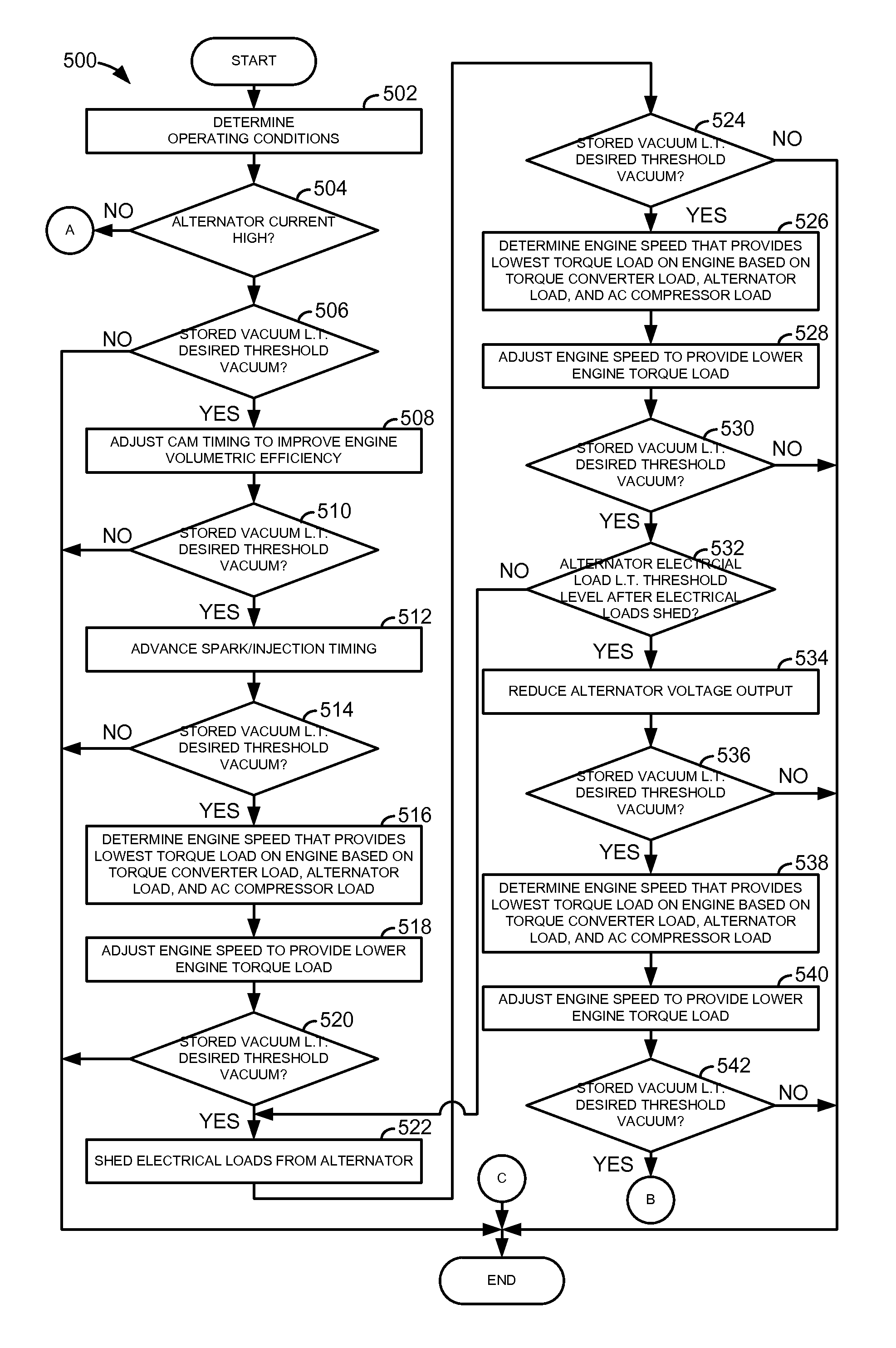
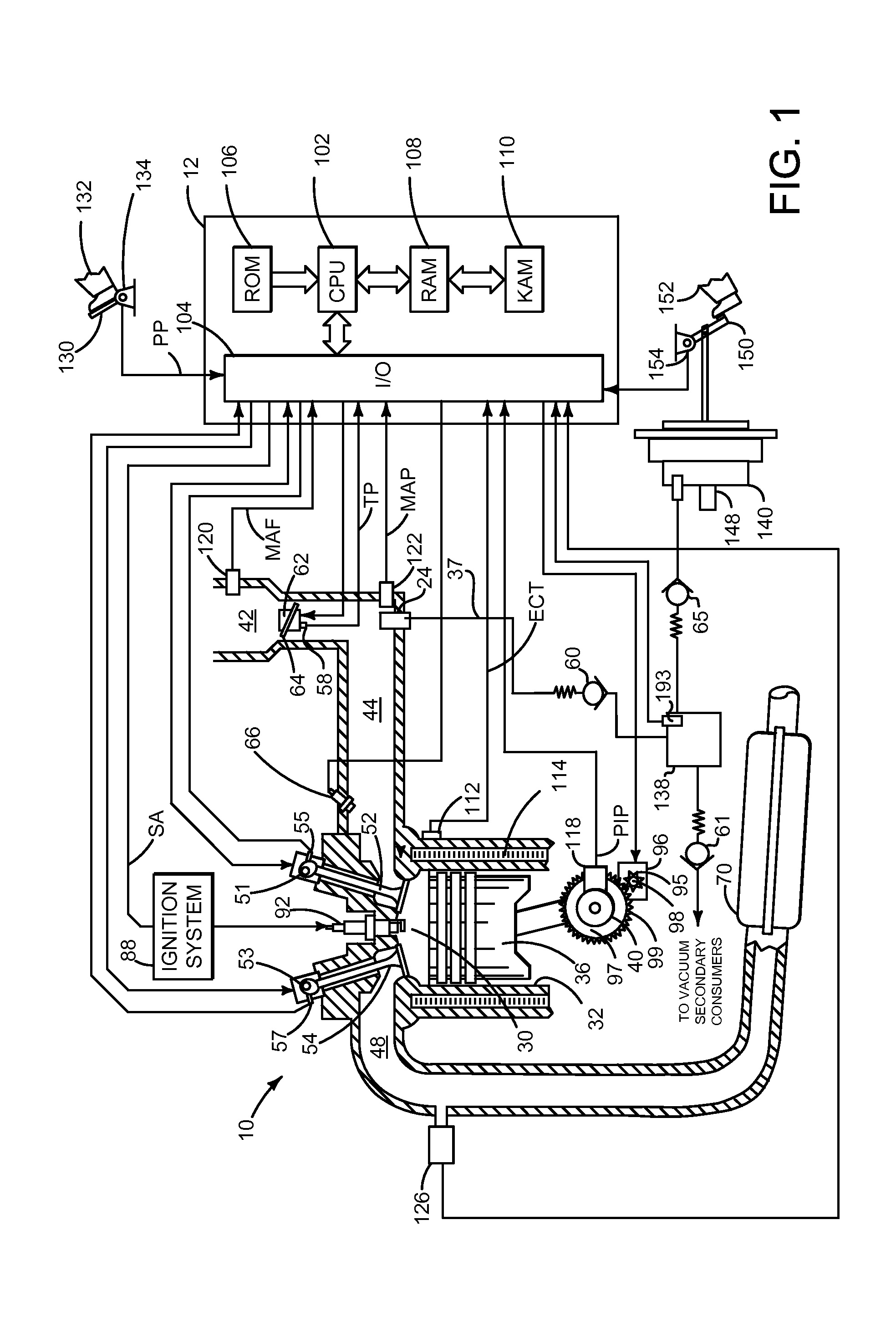
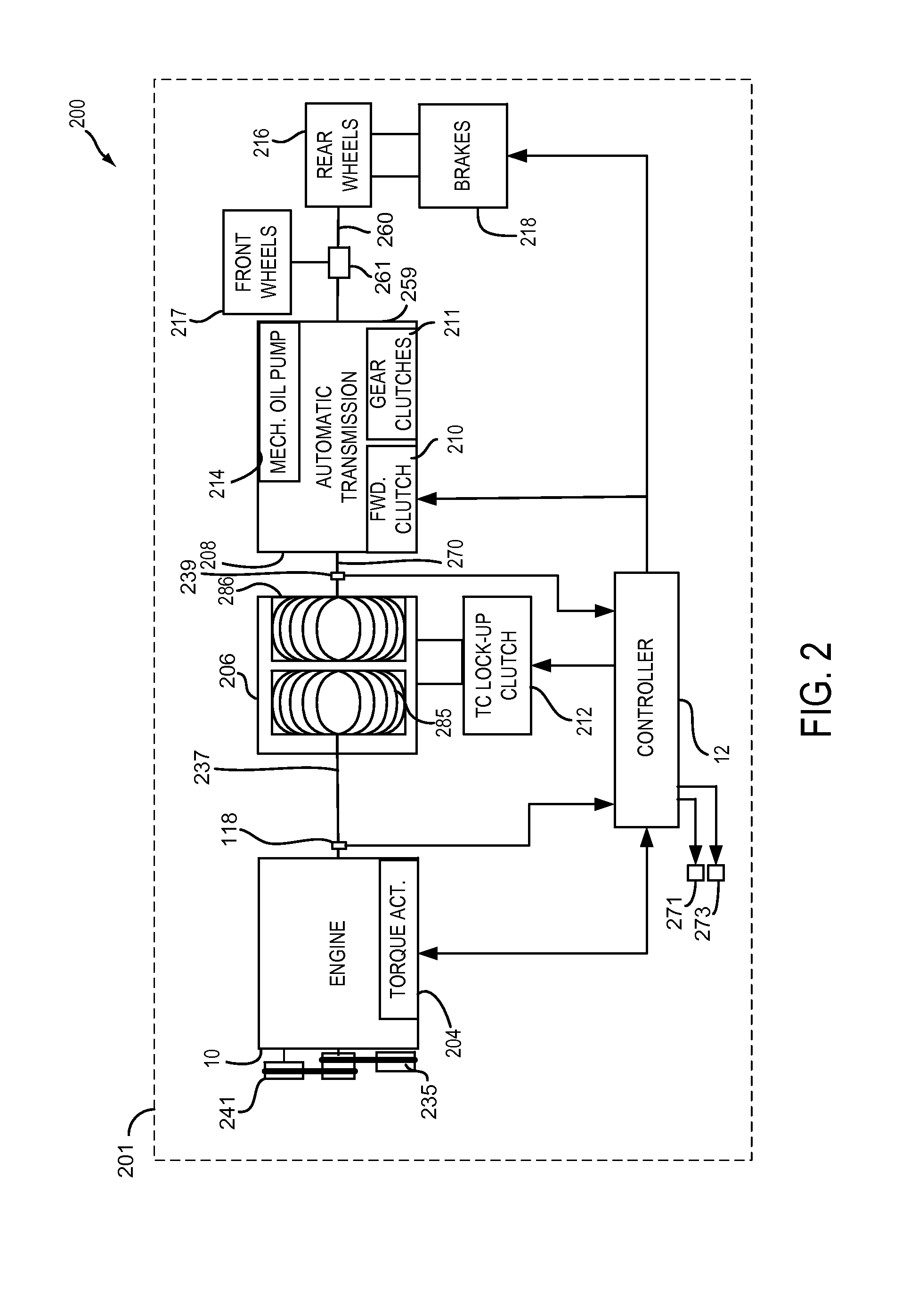
[0014]The present description is related to controlling a vehicle powertrain. The vehicle may include an engine and transmission as is shown in FIGS. 1-2. The engine may include engine speed dependent devices that apply load to the engine and provide ancillary functions. Loads applied to the engine via the engine speed dependent devices and engine speed and may be controlled as shown in FIG. 4 according to the method illustrated in the flowchart of FIGS. 5 and 6.

[0015]Referring to FIG. 1, internal combustion engine 10, comprising a plurality of cylinders, one cylinder of which is shown in FIG. 1, is controlled by electronic engine controller 12. Engine 10 includes combustion chamber 30 and cylinder walls 32 with piston 36 positioned therein and connected to crankshaft 40. Flywheel 97 and ring gear 99 are coupled to crankshaft 40. Starter 96 includes pinion shaft 98 and pinion gear 95. Pinion shaft 98 may selectively advance pinion gear 95 to engage ring gear 99. Starter 96 may be di...


PUM


Abstract

A method and system for improving vacuum generation for a vehicle is described. In one example, engine speed and alternator load are adjusted in an alternating manner to increase and amount of vacuum provide by an engine to a vacuum reservoir.

Description

FIELD[0001]The present description relates to a method and system for providing vacuum for a vehicle. The method and system may be particularly useful for vehicles that include small displacement engines.BACKGROUND AND SUMMARY[0002]Vacuum may be used as a device actuating medium in a vehicle. For example, vacuum may be used to assist a driver applying vehicle brakes. In particular, vacuum operates on a brake booster diaphragm to increase an amount of force applied to vehicle brakes when a driver depresses a brake pedal. However, if the vehicle includes a smaller displacement engine, it may be difficult for the engine to provide as much vacuum as is desired via its intake manifold or an ejector. One way of improving an amount of vacuum generated by an engine is to reduce engine load so that less air is necessary to keep the engine running. However, it may not always be possible to reduce engine load when additional vacuum is desired. Further, even if some loads can be shed from the e...

Claims


Application Information

Patent Timeline
IPC IPC(8): F02D31/00
CPCF02D31/001B60W2710/0683F02D37/02F02D2041/001F02D2200/101F02D2250/18F02D2250/24F02D2250/41F02D2400/12
Inventor PURSIFULL, ROSS DYKSTRA
Owner FORD GLOBAL TECH LLC
Why Eureka
Try Eureka