System and method for generating vacuum for a vehicle

a technology for vacuum consumers and vehicles, applied in machines/engines, combustion-air/fuel-air treatment, lighting and heating apparatus, etc., can solve the problems of more difficult to produce vacuum via the engine at higher altitudes, more difficult to reduce the torque of the engine, and more cost-effective effects

Active Publication Date: 2017-01-10
FORD GLOBAL TECH LLC
View PDF2 Cites 0 Cited by
  • Summary
  • Abstract
  • Description
  • Claims
  • Application Information

AI Technical Summary

Benefits of technology

[0002]Vacuum may be used in a vehicle as a motive force for adjusting a position of actuators, assisting adjustment of an actuator, and / or as a way of transferring gases from one location to another location. For example, vacuum may assist a driver applying a vehicle's brake pedal or purging fuel vapors from a fuel vapor storage canister to an engine. One way to generate vacuum is to operate an engine throttled. At lower engine loads, the engine's throttle may be partially closed to reduce engine torque. Vacuum may be generated within the engine's air intake system at a location downstream of the throttle. Thus, the engine may be a cost effective way of producing vacuum. However, smaller displacement engines tend to operate at higher intake manifold pressure as compared to larger displacement engines. Additionally, when an engine is operated at higher altitudes, it may be more difficult for the engine to produce vacuum since air pressure at higher altitudes is reduced as compared to air pressure at sea level. Consequently, an engine may operate less throttled at higher altitudes to produce a same amount of torque as at a lower altitude. Therefore, it may be more difficult to produce vacuum via the engine at higher altitudes.
[0003]One way of generating additional vacuum at higher altitudes is to reduce a load applied to the engine when the engine is operated at higher altitudes. However, it may not be possible or desirable to reduce a load applied to an engine every time vacuum is requested without degrading operation of the device providing load to the engine. As a result, the engine may produce lower vacuum than is desired, or vehicle passengers may become aggravated by degraded performance of subsystems that are unloaded from the engine for extended periods to improve vacuum generation.
[0005]By opening an air conditioning compressor bypass valve in response to a request for vacuum, it may be possible to provide the technical result of producing vacuum for vehicle systems in a way that is less noticeable to vehicle occupants. In particular, an air conditioning compressor bypass valve may be opened for short time periods (e.g., less than five seconds) to unload the air conditioning compressor from the engine. Thus, the air conditioning compressor may be unloaded from the engine for short periods of time so that vacuum in a vacuum reservoir may be replenished. Additionally, opening the air conditioning compressor bypass clutch allows an air conditioning compressor clutch to remain closed so that there may be less possibility of air conditioning clutch degradation.
[0007]The present description may provide several advantages. Namely, the approach may improve vacuum generation for a vehicle. Additionally, the approach may reduce the possibility of air conditioning clutch degradation. Further, the approach may reduce vehicle passenger discomfort by reducing air conditioning compressor load on an engine for short intervals during which a reduction in air conditioning system output may be less noticeable.

Problems solved by technology

However, smaller displacement engines tend to operate at higher intake manifold pressure as compared to larger displacement engines.
Additionally, when an engine is operated at higher altitudes, it may be more difficult for the engine to produce vacuum since air pressure at higher altitudes is reduced as compared to air pressure at sea level.
Therefore, it may be more difficult to produce vacuum via the engine at higher altitudes.
However, it may not be possible or desirable to reduce a load applied to an engine every time vacuum is requested without degrading operation of the device providing load to the engine.
As a result, the engine may produce lower vacuum than is desired, or vehicle passengers may become aggravated by degraded performance of subsystems that are unloaded from the engine for extended periods to improve vacuum generation.
Additionally, the approach may reduce the possibility of air conditioning clutch degradation.

Method used


Image

  • System and method for generating vacuum for a vehicle
  • System and method for generating vacuum for a vehicle
  • System and method for generating vacuum for a vehicle

Examples


Embodiment Construction

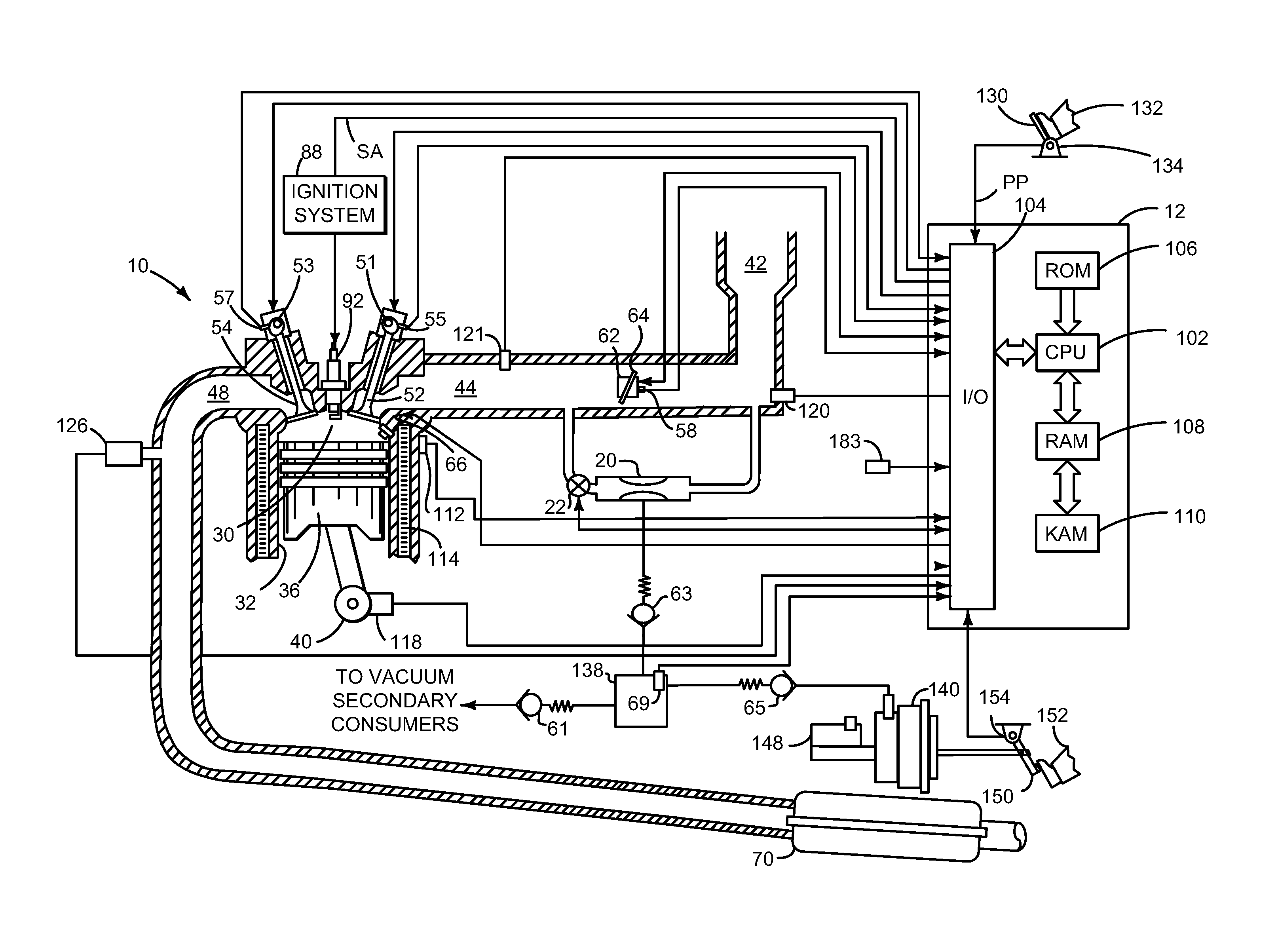
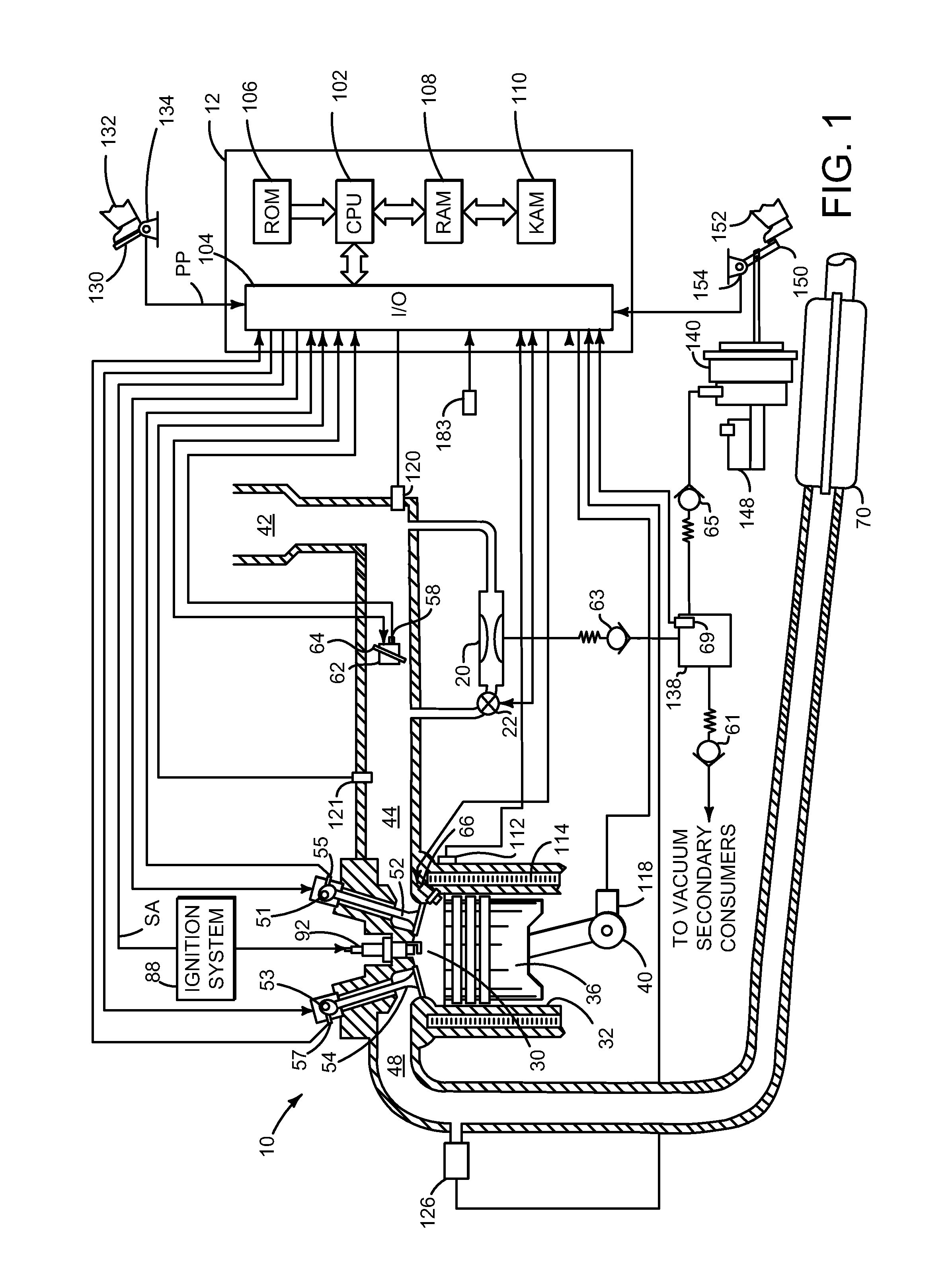
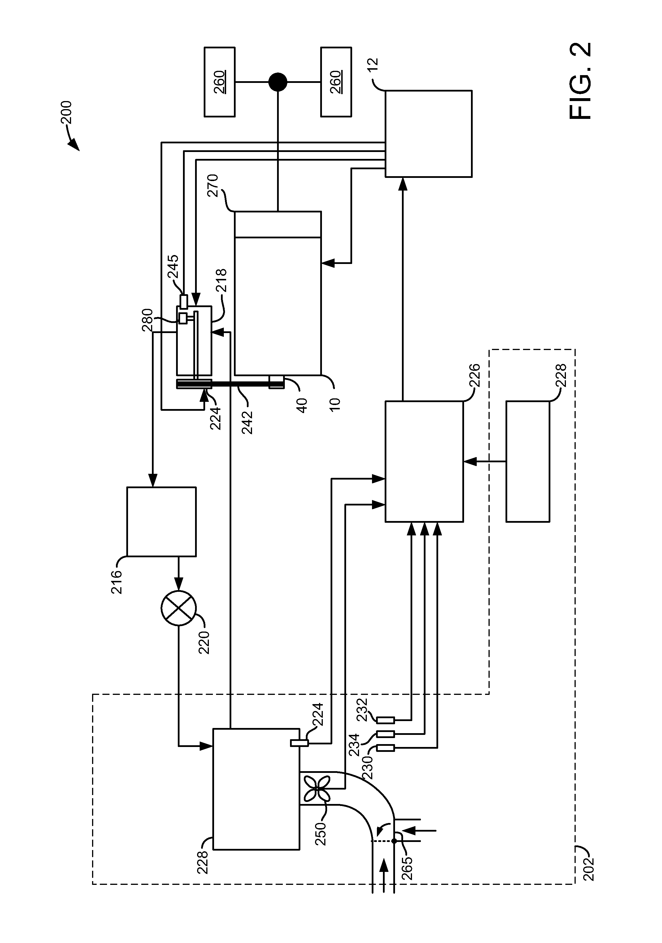
[0016]The present description is related to providing vacuum to a vehicle. Vacuum is provided by an engine to a vacuum reservoir as shown in FIG. 1. The engine may be included in a vehicle that includes an air conditioning system as shown in FIGS. 2-4. The air conditioning system may be operated as shown in the sequence of FIG. 5 to improve vacuum generation within an engine. The method of FIG. 6 describes a way of controlling load applied to an engine so that the engine may provide vacuum while at the same time reducing the possibility of aggravating passengers due to loss of operation of vehicle systems while generating vacuum.

[0017]Referring to FIG. 1, internal combustion engine 10, comprising a plurality of cylinders, one cylinder of which is shown in FIG. 1, is controlled by electronic engine controller 12. Engine 10 includes combustion chamber 30 and cylinder walls 32 with piston 36 positioned therein and connected to crankshaft 40. Combustion chamber 30 is shown communicating...


PUM


Abstract

Systems and methods for improving generation of vacuum for a vehicle are disclosed. In one example, an air conditioning compressor bypass valve is selectively activated to improve generation of vacuum by an engine. The systems and methods may reduce the possibility of compressor clutch degradation.

Description

FIELD[0001]The present description relates to systems and methods for generating vacuum for vacuum consumers of a vehicle. The systems and methods may be particularly useful for vehicles that operate at higher altitudes.BACKGROUND AND SUMMARY[0002]Vacuum may be used in a vehicle as a motive force for adjusting a position of actuators, assisting adjustment of an actuator, and / or as a way of transferring gases from one location to another location. For example, vacuum may assist a driver applying a vehicle's brake pedal or purging fuel vapors from a fuel vapor storage canister to an engine. One way to generate vacuum is to operate an engine throttled. At lower engine loads, the engine's throttle may be partially closed to reduce engine torque. Vacuum may be generated within the engine's air intake system at a location downstream of the throttle. Thus, the engine may be a cost effective way of producing vacuum. However, smaller displacement engines tend to operate at higher intake mani...

Claims


Application Information

Patent Timeline
Patent Type & Authority Patents(United States)
IPC IPC(8): F25B1/00F02M35/10F02D9/10B60H1/32F17D5/00F02D9/02
CPCF17D5/00B60H1/3204F02D9/1055F02M35/10229Y10T137/86019F02D2009/024F02D2250/24F02D2250/41Y10T137/0379B60H1/32
Inventor CUNNINGHAM, RALPH WAYNEPURSIFULL, ROSS DYKSTRA
Owner FORD GLOBAL TECH LLC
Why Eureka
Try Eureka