Method and device for operating an internal combustion engine

a technology of internal combustion engine and operating point, which is applied in the direction of machines/engines, electric control, instruments, etc., can solve the problems of escaping harmful hc emissions into the environment, changing the operating point of the engine, and affecting the operation of the engin

Inactive Publication Date: 2005-02-03
ROBERT BOSCH GMBH
View PDF6 Cites 83 Cited by
  • Summary
  • Abstract
  • Description
  • Claims
  • Application Information

AI Technical Summary

Benefits of technology

[0004] In contrast, the method and the device according to an example embodiment of the present invention for operating an internal combustion engine may provide the advantage over conventional methods and devices in that at least one pressure differential is ascertained between an intake-manifold pressure, or an ambient pressure, on the one hand, and a pressure in the ventilation duct, on the other hand, and that a fault in the ventilation is diagnosed as a function of the at least one pressure differential. In this manner, faults in the ventilation may also be diagnosed in internal combustion engines in which the load is detected by an intake-manifold pressure sensor. As a result, leakages or disconnected hoses of the ventilation or ventilation duct may be detected in a reliable manner. In internal combustion engines in which the load is detected by an air-mass flow sensor, a fault in the ventilation may be located unequivocally, and leakages or disconnected hoses of the ventilation or the ventilation duct, for example, may be detected in a reliable manner.

Problems solved by technology

The result of a defect in the crankcase-ventilation system is, first of all, the escape of harmful HC emissions into the environment and, secondly, a changed operating point of the engine, especially during idling.
When intake-manifold pressure sensors are used, such a defect will not lead to a mixture deviation since the measured intake-manifold pressure is always correct and it is basically unimportant from where the combustion air comes.
In this manner, faults in the ventilation may also be diagnosed in internal combustion engines in which the load is detected by an intake-manifold pressure sensor.

Method used


Image

  • Method and device for operating an internal combustion engine
  • Method and device for operating an internal combustion engine
  • Method and device for operating an internal combustion engine

Examples


Embodiment Construction

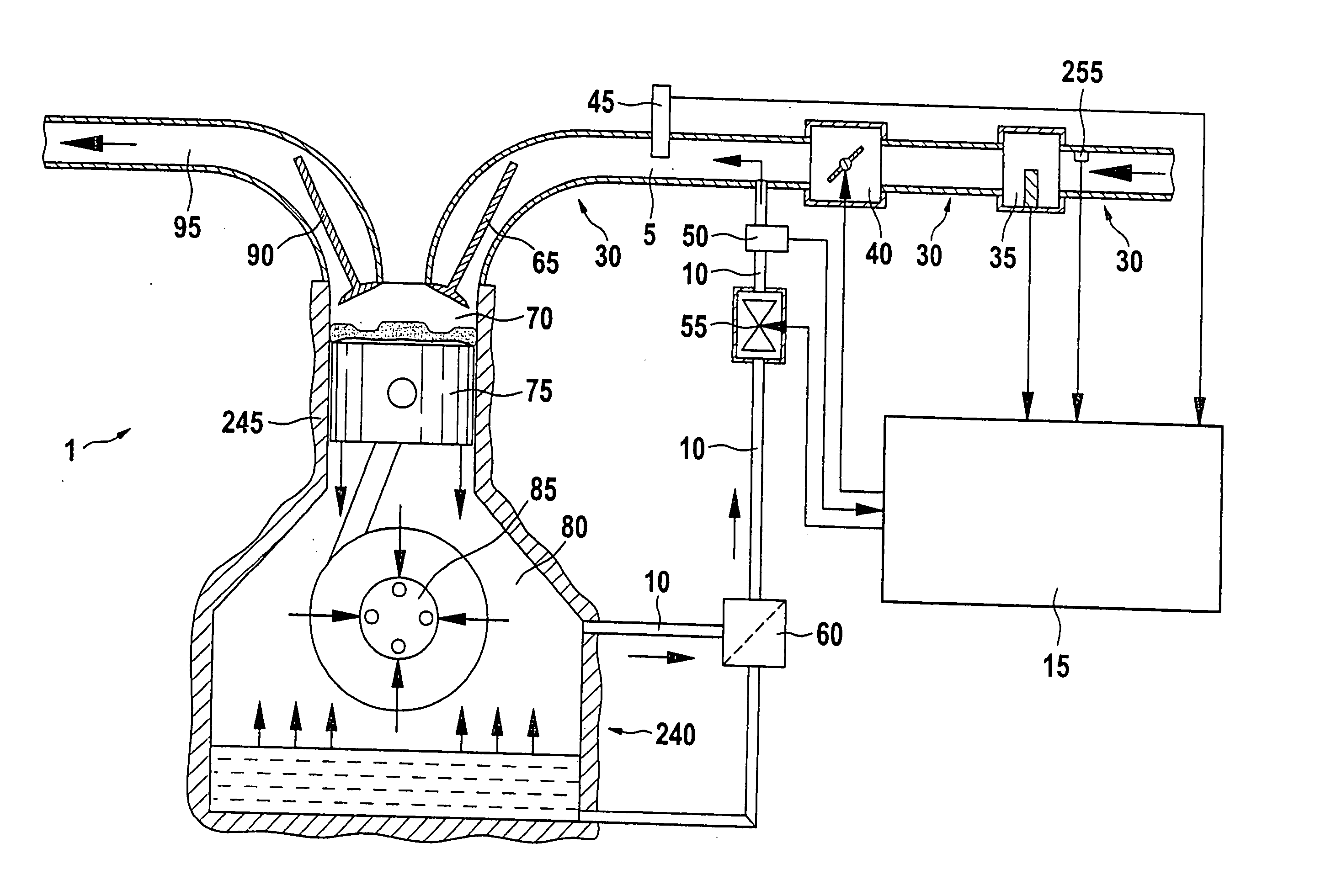
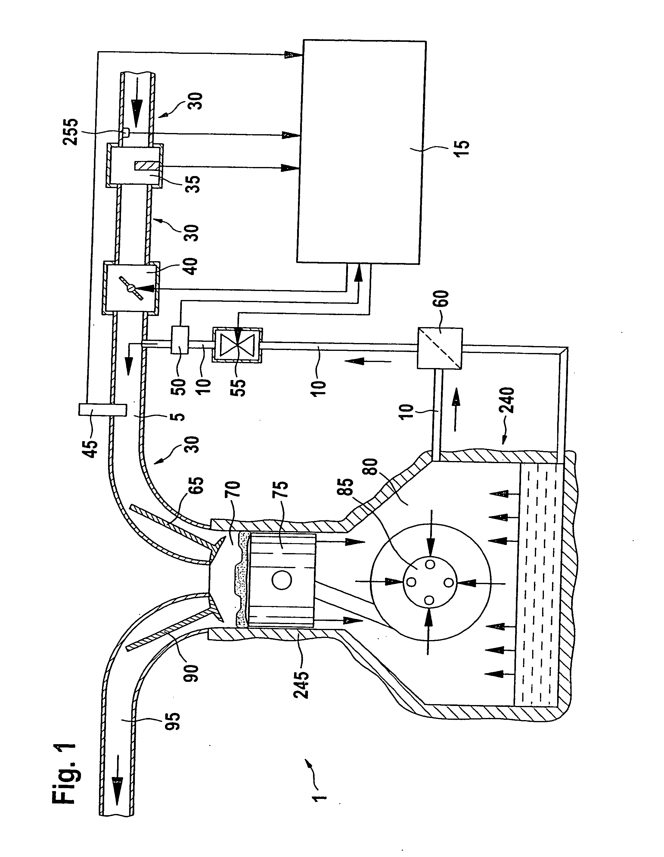
[0029] In FIG. 1, reference numeral 1 designates an internal combustion engine as a whole, the combustion engine belonging to a motor vehicle, for example. Internal combustion engine 1 includes a combustion engine 240, which may be embodied as a spark-ignition engine or as a diesel engine, for instance. In the following, for example, internal combustion engine 240 may be a spark-ignition engine. FIG. 1 shows one of possibly several cylinders of spark-ignition engine 240. The cylinder is indicated by reference numeral 245 in FIG. 1. Via an intake valve 65, an intake manifold 5 conducts air to a combustion chamber 70 of cylinder 245. Intake manifold 5 is part of an air supply 30 and represents the part of air supply 30 between a throttle valve 40 and an intake valve 65. Arranged in intake manifold 5 is an intake-manifold pressure sensor 45. Intake-manifold pressure sensor 45 measures the intake-manifold pressure pi in intake manifold 5 and conveys the measuring result to an engine con...


PUM


Abstract

A method and a device for operating an internal combustion engine having an intake manifold and a ventilation system may allow a reliable and fault-free diagnosis of a fault in the ventilation. The ventilation system may be a tank ventilation or a crankcase ventilation. The ventilation duct is conducted to the intake manifold of the internal combustion engine. At least one pressure differential may be determined between an intake-manifold pressure or an ambient pressure, on the one hand, and a pressure in the ventilation duct, on the other hand. A fault in the ventilation may be diagnosed as a function of the at least one pressure differential.

Description

CROSS-REFERENCE TO RELATED APPLICATIONS [0001] The present application claims priority to Application No. 103 20 054.1, filed in the Federal Republic of Germany on May 6, 2003, which is expressly incorporated herein in its entirety by reference thereto. FIELD OF THE INVENTION [0002] The present invention relates to a method and a device for operating an internal combustion engine. BACKGROUND INFORMATION [0003] Spark-ignition engines are provided with crankcase-ventilation systems. The “blow-by” gases, which are mixed with engine oil and flow from the combustion chamber past the piston of a cylinder into the crankcase, are first conducted to a liquid-vapor separator and then returned to the intake system of the engine for combustion, this return taking place at a suitable location where negative pressure is ideally present in nearly all operating states of the engine. To limit the negative pressure in the crankcase, a calibrated throttle valve is integrated in the ventilation duct. I...

Claims


Application Information

Patent Timeline
Patent Type & Authority Applications(United States)
IPC IPC(8): F01M11/10F02D45/00F01M13/02F02D41/00F02D41/22F02M25/06F02M25/08G01M99/00
CPCF01M11/10F01M13/023F01M2011/1446F02D41/0027F02D41/22F16N2250/05F02D2200/703F02M25/06F02M25/0827F16N2250/04F02D2200/0406
Inventor BEYER, HANS-ERNSTKASTNER, FRANK
Owner ROBERT BOSCH GMBH
Why Eureka
Try Eureka