Fuel system with dual fuel injectors for internal combustion engines

a fuel system and internal combustion engine technology, applied in the direction of machines/engines, electric control, mechanical equipment, etc., can solve the problems of non-compliance with applicable emissions regulations, difficult production of reliable, efficient, cost-effective, gaseous-fueled heavy-duty engines,

Inactive Publication Date: 2002-04-16
ECONTROLS LLC
View PDF13 Cites 86 Cited by
  • Summary
  • Abstract
  • Description
  • Claims
  • Application Information

AI Technical Summary

Problems solved by technology

However, producing a reliable, efficient, cost-effective, heavy-duty, gaseous-fueled engine has proved to be a difficult task.
Such lean-burn engines typically operate very close to the lean flammability limit of the fuel-air mixture.
If the engine operates slightly rich of the desired equivalence ratio, emissions will increase significantly and may result in non-compliance with applicable emissions regulations.
On the other hand, if the engine operates slightly lean of the desired equivalence ratio, the engine may misfire, which adversely affects engine performance, driveability, and emissions.
In the real world, however, this almost never occurs; instead, one cylinder will misfire before the others.
The effects of the above factors may be minimized with careful design and development practices, but they cannot be eliminated.
Multipoint fuel injection (MPI) offers control of fuel on an individual cylinder basis, which satisfies the control requirements for factors (3) through (10) above, but MPI has the disadvantages of higher fuel mal-distribution among cylinders due to injector flow variations, high sensitivity to those mal-distribution errors, reduced mixing time, and high fuel supply pressure.
Historically, however, MPI systems have been used to control fuel on a macro level only (replacing the TBI); no successful attempt has been made to trim (tailor) the fuel flow on an individual cylinder basis.
Currently, no existing lean-burn fuel system provides the level of control required to simultaneously optimize engine performance, driveability, and emissions while maintaining a robust calibration.
The engine is usually calibrated richer than optimum to provide an acceptable margin from misfire and good driveability, but such a calibration results in higher than optimum NOx emissions.
Current emissions regulations allow this type of compromise to exist, but lower emissions standards are in the process of being implemented, and soon such a rich calibration will not be an accepted practice.

Method used


Image

  • Fuel system with dual fuel injectors for internal combustion engines
  • Fuel system with dual fuel injectors for internal combustion engines
  • Fuel system with dual fuel injectors for internal combustion engines

Examples


Embodiment Construction

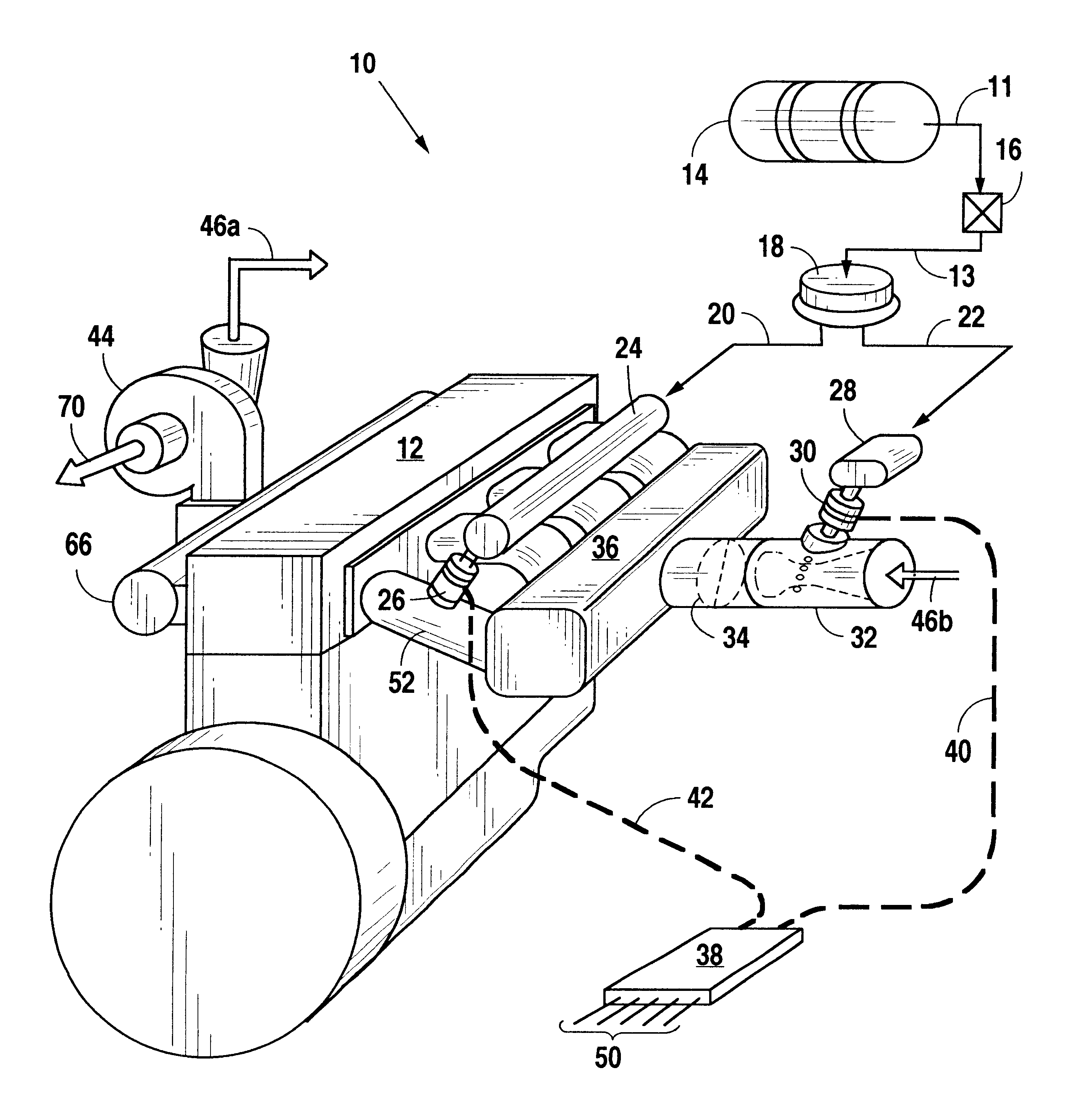
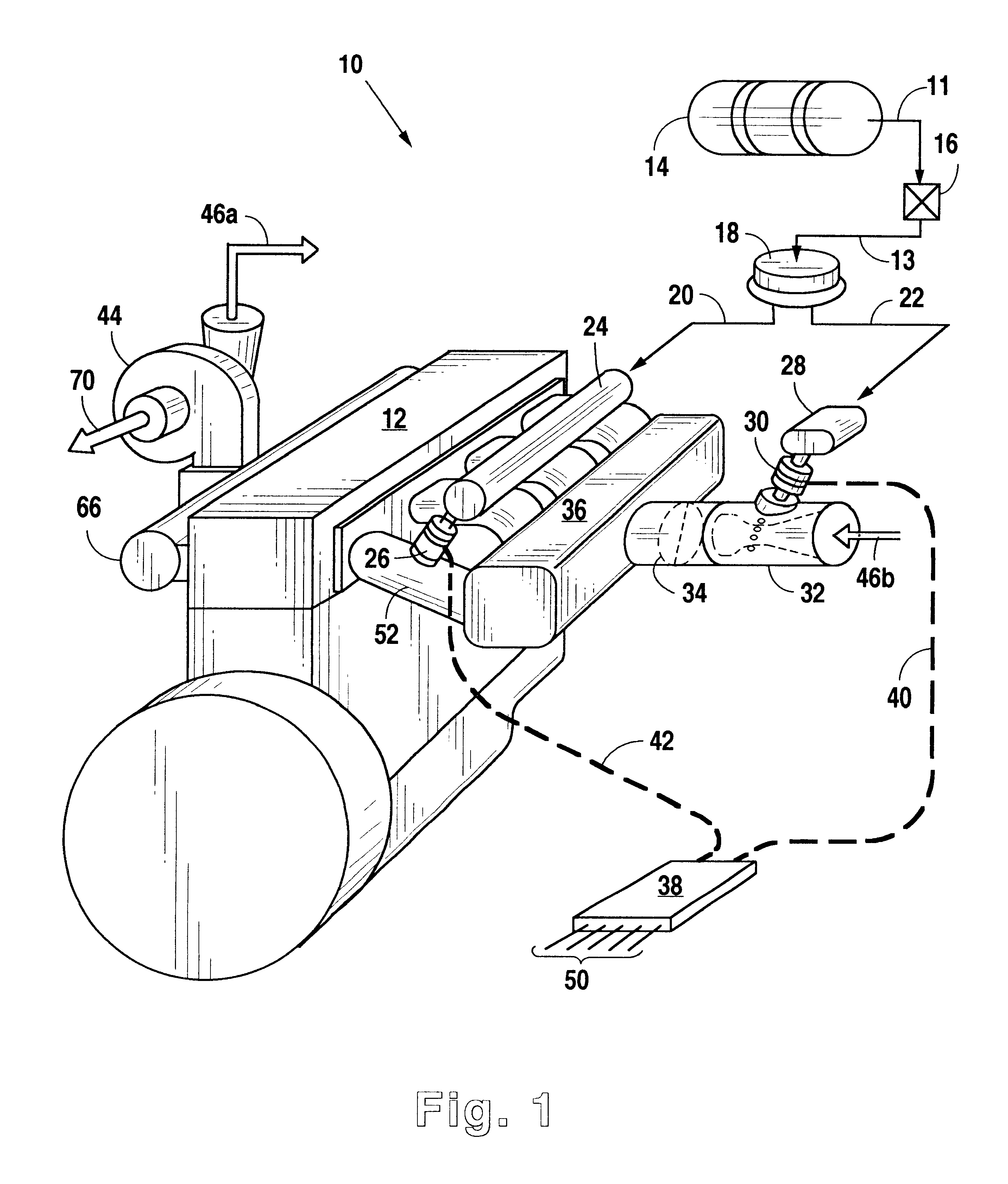
FIG. 1 illustrates a preferred fuel system 10 in accordance with the present invention that is used to supply fuel, preferably gaseous fuel, to a multi-cylinder, turbocharged engine 12. With respect to the fuel in system 10, the term "fluid" is used herein to mean either a liquid or a gas. The fuel supply / storage of system lo may be any of a number of commonly available fuel supply systems, such as stationary gas pipelines, compressed gas cylinders, or liquefied storage tanks. Preferably, fuel system 10 contains a fuel storage cylinder 14 that feeds fuel to the rest of system 10 through a fuel tube or supply line 11, which preferably includes an emergency shut-off valve 16 and may also include a fuel filter (not shown). Downstream of emergency shut-off valve 16, the fuel passes through fuel line 13 to a fuel pressure regulator 18, which regulates the pressure of the fuel according to methods well known in the art. From pressure regulator 18, the fuel is fed through supply lines 20 a...


PUM


Abstract

This invention is directed to an apparatus and method for providing improved control of fuel, preferably gaseous fuel, to an internal combustion engine such that each cylinder of the engine will operate within a predetermined tolerance off of its lean misfire limit. The disclosed system introduces fuel to the engine at two locations: (1) upstream of the intake manifold to provide premixing of a majority of the fuel with air, and (2) near the intake valve of each cylinder for tailoring the fuel flow to each cylinder to achieve that fuel-to-air ratio which is necessary to maintain each cylinder at the desired tolerance from the lean misfire limit. Several calibration and control methods are described to maximize performance of the fuel system, including the use of a misfire detection technique to determine the lean misfire limit of each cylinder to allow the respective port fuel injector to provide a specified margin from lean misfire. The present invention enhances engine performance and driveability while reducing exhaust emissions.

Description

1. Field of the InventionThis invention relates generally to fuel supply systems for engines, and more particularly to a method and apparatus for introducing fuel to an internal combustion engine both upstream and downstream of the intake manifold.2. Description of the Related ArtWhile consumers continue to demand improved engine performance in terms of power, efficiency, reliability, and driveability, regulating bodies continue to impose stricter standards requiring further reductions in harmful exhaust emissions. As a result, engine development engineers must continually strive to develop new technologies that improve combustion performance while reducing exhaust emissions in order to meet market demands.Gaseous fuels are becoming increasingly popular for use as engine fuels due to their inherently cleaner combustion, which provides the potential for lower regulated exhaust emissions. However, producing a reliable, efficient, cost-effective, heavy-duty, gaseous-fueled engine has p...

Claims


Application Information

Patent Timeline
Patent Type & Authority Patents(United States)
IPC IPC(8): F02D35/00F02D19/02F02D19/00F02D41/14F02F1/24F02D41/34F02D41/00F02D35/02
CPCF02D35/0092F02D41/0027F02D41/008F02D41/1454F02D41/3094F02F1/242F02D19/0647F02D19/0692F02M21/0284F02D19/024F02M21/0278Y02T10/36F02D41/1441F02D2200/1015Y02T10/32F02M21/047F02M21/042F02D35/021Y02T10/30
Inventor GUGLIELMO, KENNON H.KING, STEVEN R.WALSER, MICHAEL W.
Owner ECONTROLS LLC
Why Eureka
Try Eureka