Polymer prosthesis

a polymer and prosthesis technology, applied in the field of polymer prosthesis, can solve the problems of not being able to recognize various inventive aspects, requiring special production techniques, etc., and achieve the effect of simple and fast, well controllabl

Inactive Publication Date: 2014-03-18
CR BARD INC
View PDF48 Cites 9 Cited by
  • Summary
  • Abstract
  • Description
  • Claims
  • Application Information

AI Technical Summary

Benefits of technology

[0006]The present invention enables in a prosthesis for transluminal implantation both a high radial strength and high flexibility to allow the prosthesis to bend with flexing and bending of the surrounding bodily tissue.
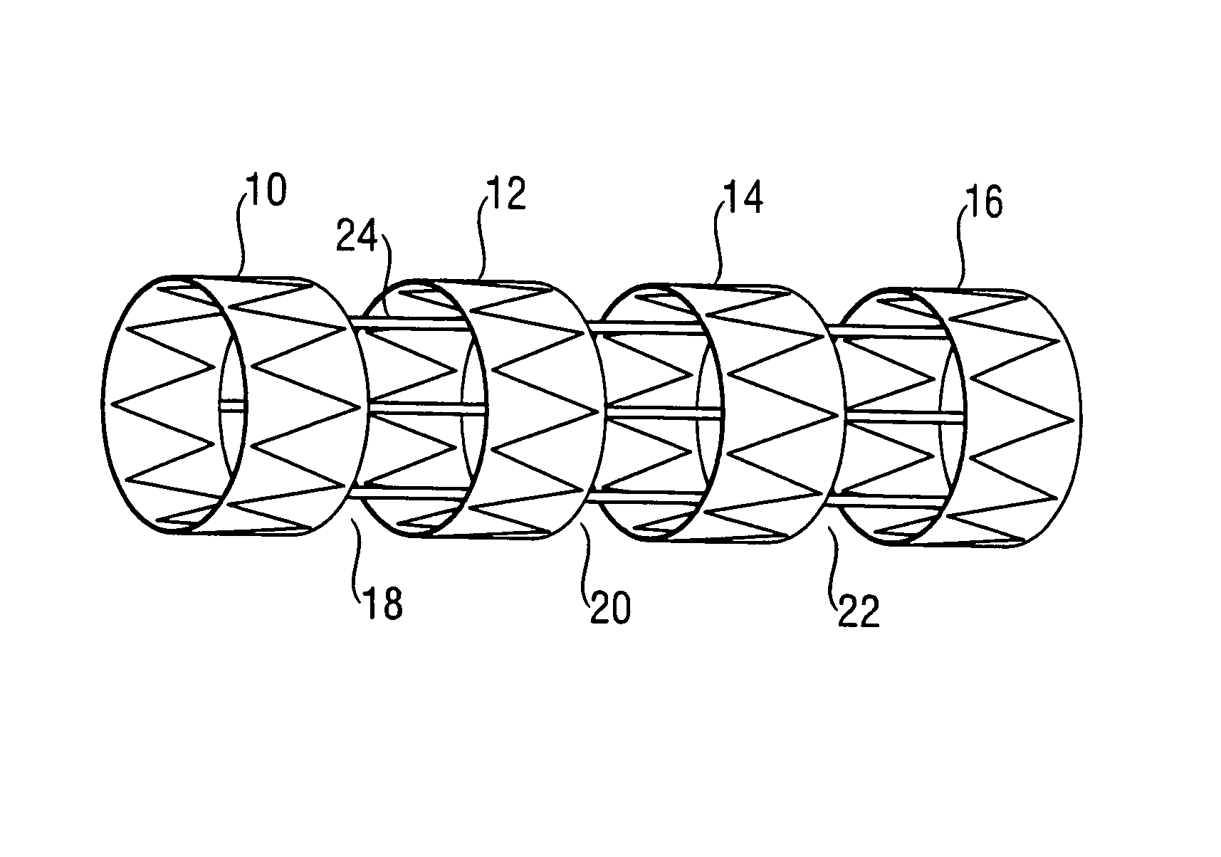
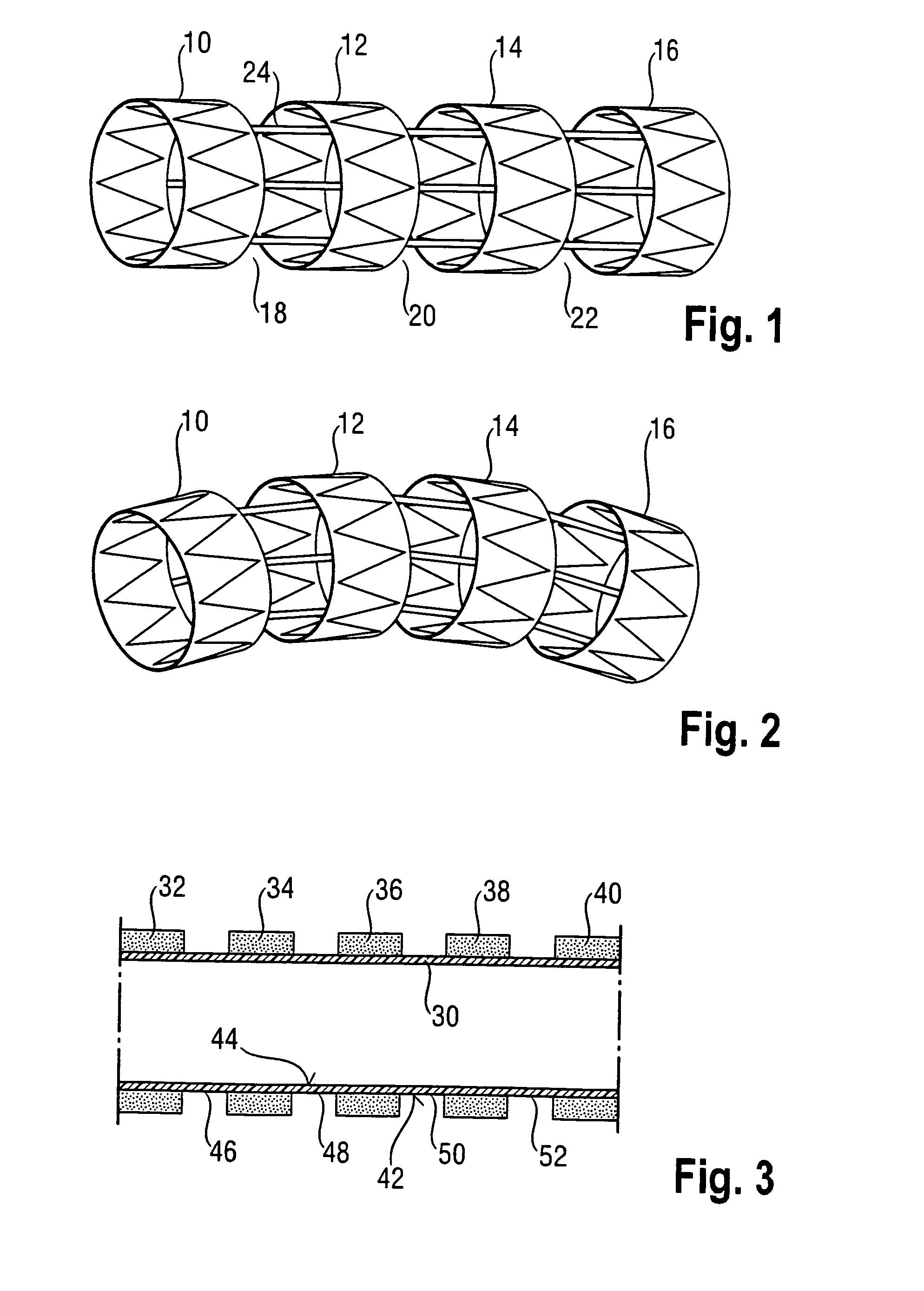
[0007]In one embodiment of the present invention there is provided a polymer prosthesis with an axial length and having in a pre-delivery condition a plurality of relatively stiff stenting segments spaced from each other along the length of the prosthesis, the spaces between the relatively stiff stenting segments of a first polymer being bridged by relatively flexible linking segments of a second polymer, different from the first, the relatively stiff stenting segments and the relatively flexible linking segments being alternatively arranged along the length of the prosthesis. The polymer prosthesis can bend with relatively little flexing of the stenting segments, by means of relatively greater flexing of the linking segments.
[0029]A large number of embodiments of a method according to the invention is available. It is, for instance, possible that the plurality of relatively flexible linking segments is provided as portions of a continuous cylindrical component of the prosthesis. This in its turn offers the possibility for bridging the relatively stiff stenting segments by attaching each of the relatively stiff stenting segments, or fixedly positioning the relatively stiff stenting segments, to the continuous cylindrical components. Such a method provides a simple and fast way of making the inventive / expanded polymer prosthesis as the linking elements themselves have already been bridged together.
[0030]In an embodiment of a method according to the invention is the continuous cylindrical component provided in the form of two concentric tubes bonded to each other by at spaced intervals along the length of the tubes and around their circumference. The reader's attention is drawn to WO 2001 / 021107 which describes a possible result of such method steps. However, it is to be noted that according to this prior art document an inflatable space between the two concentric tubes is injected with a fluid when the concentric tubes as bonded together are at the delivery side in a body. In contrast, in an embodiment of a method according to the invention will the first polymer which will form at least a part of the plurality of relatively stiff stenting segment be inserted between the concentric tubes while the cylindrical component is still outside the body, i.e. when the component is in a pre-delivery stage. This has the advantage that the making of the polymer prosthesis is very well controllable by the manufacturer of the polymer prosthesis, can be “tailor-made”, and for instance be tested before employment.
[0033]Selection of specific polymers is not of the essence of the present proposal. As indicated above, the published art is replete with discussion of synthetic polymers suitable for making implantable prostheses. The appropriate skilled person will be well able to select from amongst the candidate materials, once informed by the present application of the working principle of the present invention, namely, relatively strong stenting segments capable of pushing bodily tissue radially outwardly, interspersed with relatively soft linking segments that allow a prosthesis as a whole to bend with movements of the bodily tissue in which it is implanted.

Problems solved by technology

However, building stents from a composite of metal and polymer requires special production techniques.
However, in all of these prior proposals, there is no recognition of various inventive aspects disclosed herein.

Method used


Image

  • Polymer prosthesis
  • Polymer prosthesis
  • Polymer prosthesis

Examples


third embodiment

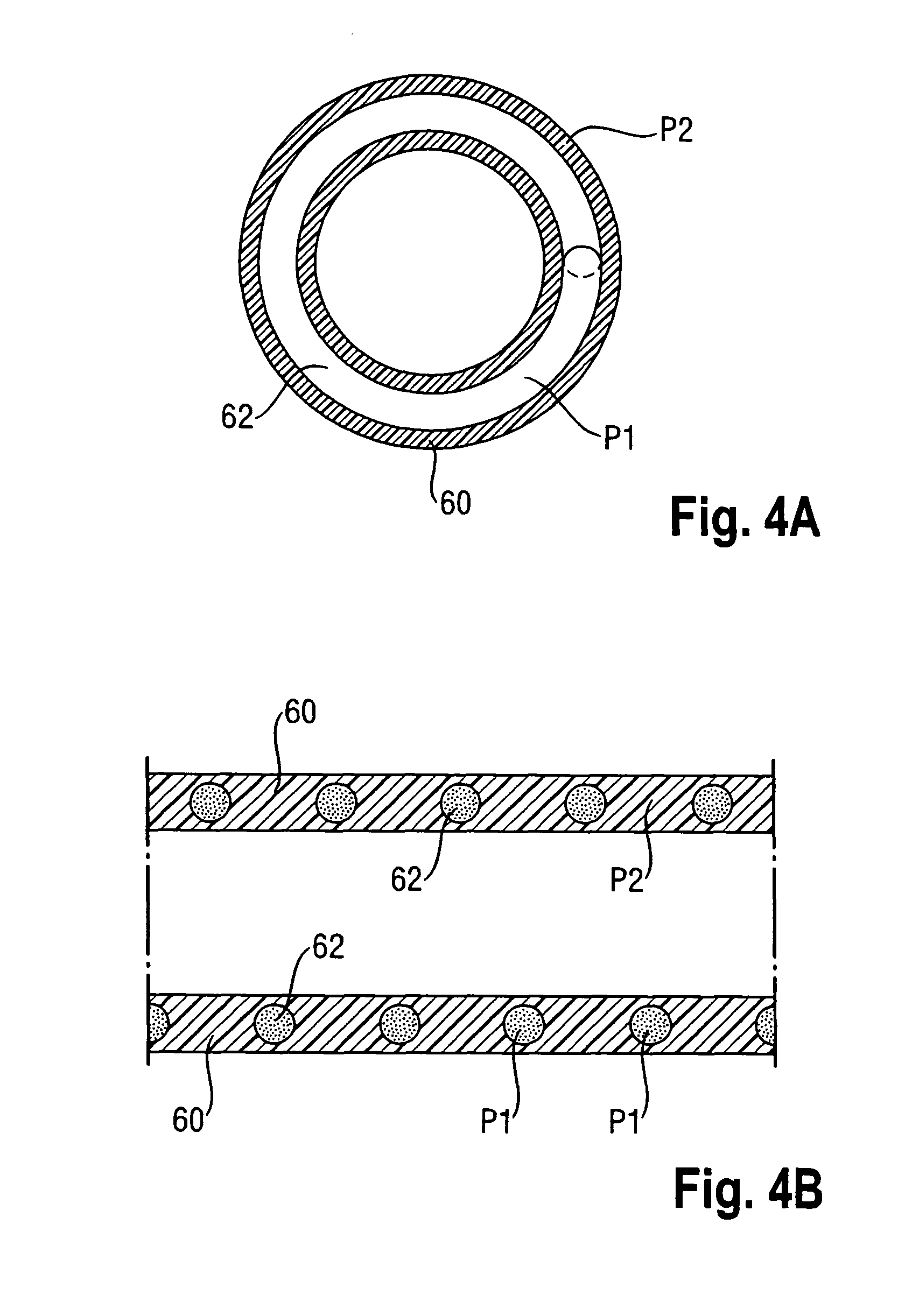
[0062]FIG. 4A-8B show schematically cross-sections of embodiments of a polymer prosthesis in accordance with the present invention. More in particular, FIG. 4A and FIG. 4B each show cross-sections of a third embodiment, wherein the polymer P1 of the relatively stiff stenting segments 62, is encapsulated between two layers of polymer P2 of the relatively flexible linking segments 60, which are in a form of two concentric layers of ePTFE.

fourth embodiment

[0063]FIGS. 5A and 5B each show cross-sections of a fourth embodiment, wherein the polymer P1 of the relatively stiff stenting segments 62 is positioned radially outwardly from the cylindrical component 60, acting here as the plurality of relatively flexible linking segment as portions of the continuous cylindrical component 60, which is preferably of ePTFE.

fifth embodiment

[0064]FIG. 6A and FIG. 6B each show cross-sections of a fifth embodiment similar to the embodiment shown in FIGS. 5A and 5B. However, in FIGS. 6A and 6B the polymer P1 of the relatively stiff stenting segments is positioned at least partly within interstices formed in the polymer P2 of the plurality of relatively flexible linking segments, here again shown in the form of a continuous cylindrical component 60, preferably made of ePTFE.


PUM


Abstract

A polymer prosthesis with lumen and an axial length and having in a pre-delivery condition a plurality of relatively stiff stenting segments spaced from each other along the length of the prosthesis, the spaces between the relatively stiff stenting segments of a first polymer being bridged by relatively flexible linking segments of a second polymer, different from the first, the relatively stiff stenting segments and the relatively flexible linking segments being alternately arranged along the length of the prosthesis.

Description

PRIORITY[0001]This application is a United States National Stage Application under 35 U.S.C. §371 of International Patent Application No. PCT / EP2006 / 008217, filed Aug. 21, 2006, which claims the benefit to United Kingdom Patent Application No. 0517085.7, filed Aug. 19, 2005, each of which is incorporated by reference into this application as if fully set forth herein.TECHNICAL FIELD[0002]This invention relates to a polymer prosthesis such as a stent, graft or stent-graft, and to a method for making a polymer prosthesis.BACKGROUND PRIOR ART[0003]WO 03 / 049641 discloses a cylindrical stent with a longitudinal rotational axis and a plurality of metal stenting rings arranged at spaced intervals along the axis, and carried on an apertured cylindrical polymeric mesh. The polymeric mesh being relatively flexible, the composite stent is comparatively flexible (allowing the stent cylinder to be bendy in the sense that the long axis can easily move from straight to curved configurations) while...

Claims


Application Information

Patent Timeline
Patent Type & Authority Patents(United States)
IPC IPC(8): A61F2/00A61F2/82A61F2/89A61F2/07
CPCA61F2002/828A61F2250/0018A61F2002/825A61F2/89A61F2002/072A61F2220/005A61F2220/0058
Inventor BLANK, THIEMOWILLE, THOMAS
Owner CR BARD INC
Why Eureka
Try Eureka