Lead having radially spaced apart contacts to allow for adjustability

a technology of radially spaced apart contacts and lead, which is applied in the direction of spinal electrodes, coupling device connections, therapy, etc., can solve the problems of invasiveness, time-consuming and laborious tunneling, and significant consumption of drugs to treat symptoms. , to achieve the effect of eliminating excess coiled lead

Active Publication Date: 2014-03-18
MEDTRONIC INC
View PDF6 Cites 1 Cited by
  • Summary
  • Abstract
  • Description
  • Claims
  • Application Information

AI Technical Summary

Benefits of technology

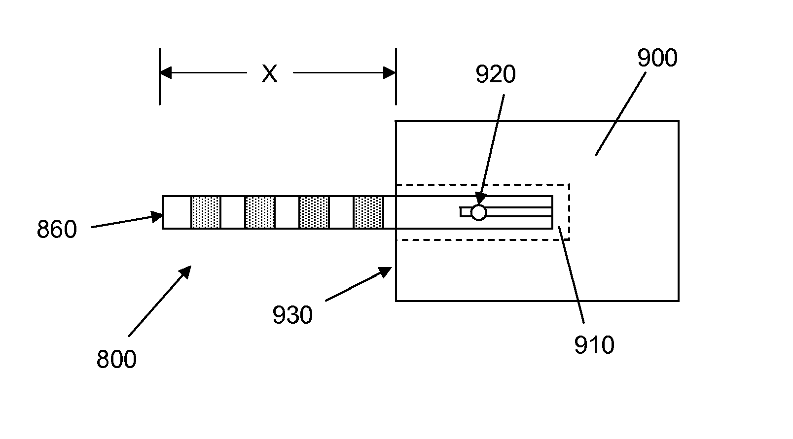
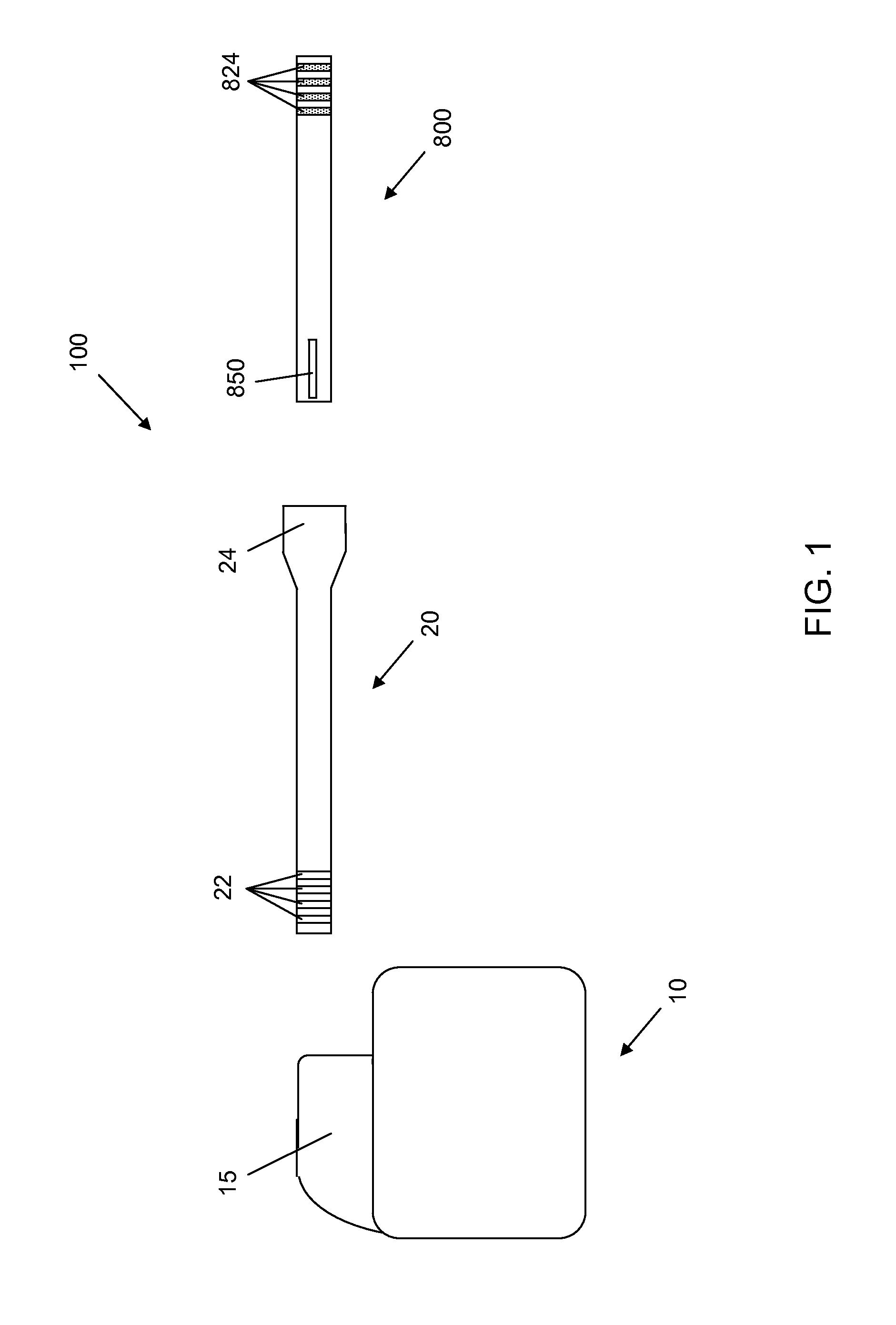
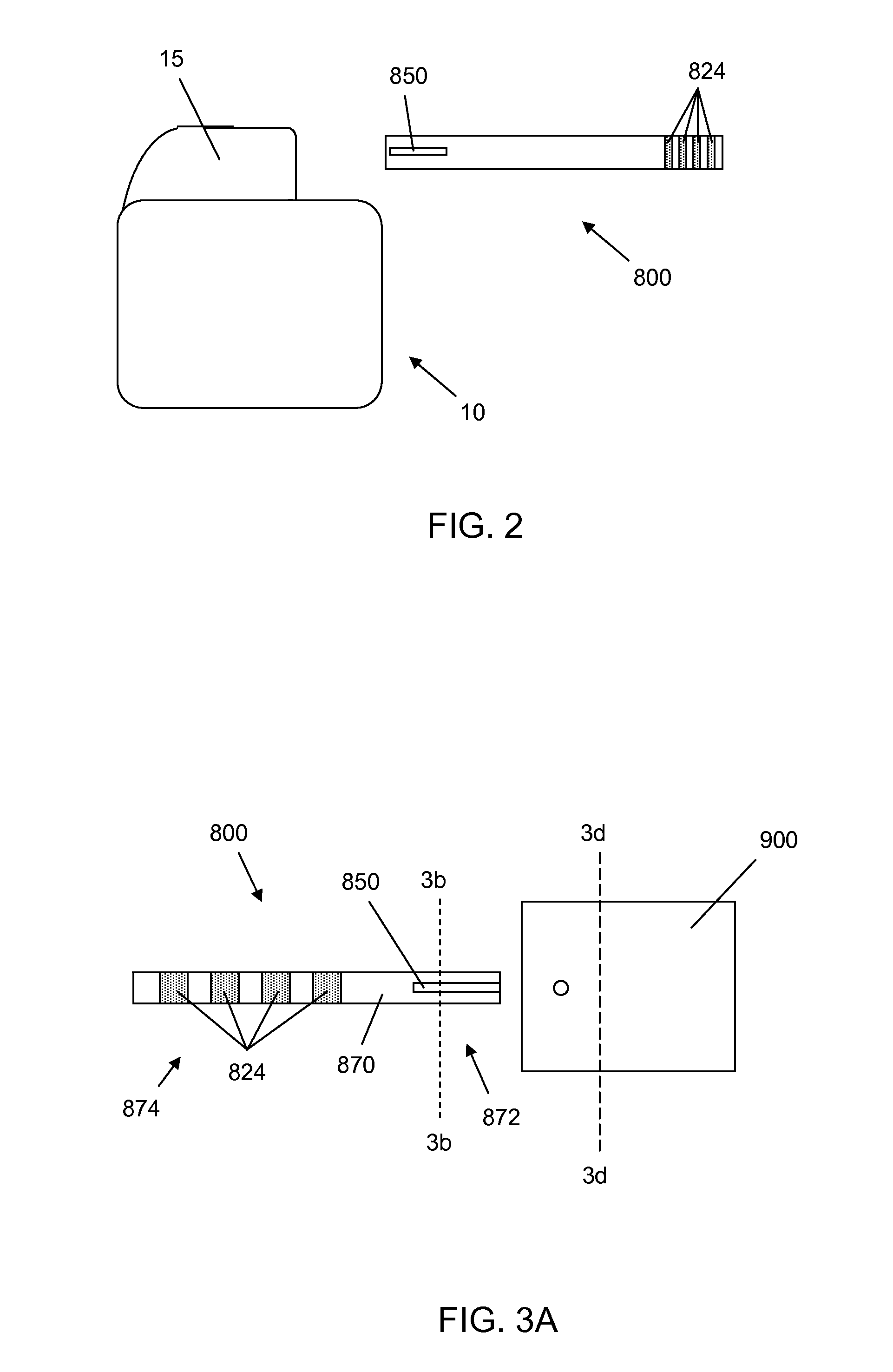
[0007]The present disclosure, among other things, describes leads having elongate radially spaced apart contacts that allow for adjustment of the length of the lead extending from an implantable medical device. Such adjustability may be sufficient to allow the lead to be properly placed during an implant procedure or may allow the lead to be used for patients with differing anatomical sizes. Such adjustability may also allow for the elimination of excess coiled lead, particularly when the lead is configured to extend only a short distance from the medical device to which the lead is configured to be coupled. Such leads may be beneficial for applying electrical stimulation signals to occipital nerves, particularly when the leads are connected to a lead extension or signal generator in proximity to the occipital nerves.

Problems solved by technology

Headaches, such as migraines, and occipital neuralgia are often incapacitating and may lead to significant consumption of drugs to treat the symptoms.
However, a rather large number of people are unresponsive to drug treatment, leaving them to wait out the episode or to resort to coping mechanisms.
Such tunneling can be time consuming and is invasive.
However, in some areas of the body, such as under the scalp, coiling or wrapping of excess lead length may be uncomfortable for the patient in which the lead is implanted or may cause lead abrasion due to, e.g., rubbing against the skull.

Method used


Image

  • Lead having radially spaced apart contacts to allow for adjustability
  • Lead having radially spaced apart contacts to allow for adjustability
  • Lead having radially spaced apart contacts to allow for adjustability

Examples


Embodiment Construction

[0025]In the following detailed description, reference is made to the accompanying drawings that form a part hereof, and in which are shown by way of illustration several specific embodiments of devices, systems and methods. It is to be understood that other embodiments are contemplated and may be made without departing from the scope or spirit of the present disclosure. The following detailed description, therefore, is not to be taken in a limiting sense.

[0026]All scientific and technical terms used herein have meanings commonly used in the art unless otherwise specified. The definitions provided herein are to facilitate understanding of certain terms used frequently herein and are not meant to limit the scope of the present disclosure.

[0027]As used in this specification and the appended claims, the singular forms “a”, “an”, and “the” encompass embodiments having plural referents, unless the content clearly dictates otherwise. As used in this specification and the appended claims, ...


PUM


Abstract

An implantable medical lead includes a lead body having a proximal portion and a distal portion. The lead also includes first and second contacts located at the proximal portion of the lead body, and includes first and second electrodes located at the distal portion of the lead body. The first electrode is electrically coupled to the first contact and the second electrode is electrically coupled to the second contact. The first contact has a proximal end and a distal end and the second contact has proximal end and a distal end. The second contact is radially spaced apart from the first contact. The contacts do not extend around the lead body. This disclosure also relates to an implantable lead extension and to an implatable signal generator having connectors configured to receive the present lead.

Description

[0001]This application claims the benefit of and is a U.S. National Stage filing under 35 U.S.C. 371 of copending PCT Application Serial No. PCT / US09 / 45577, filed May 29, 2009, which in turn claims the benefit of U.S. Provisional Application No. 61 / 058,292, filed Jun. 3, 2008 “Lead Having Radially Spaced Apart Contacts to Allow for Adjustability”, and U.S. Provisional Application No. 61 / 175,481, filed May 5, 2009, “Lead Having Radially Spaced Apart Contacts to Allow for Adjustability,” the disclosure of all of the above which is incorporated by reference herein in its entirety.FIELD[0002]The present disclosure relates to implantable medical devices; more particularly to medical leads having radially spaced apart proximal contacts.BACKGROUND[0003]Headaches, such as migraines, and occipital neuralgia are often incapacitating and may lead to significant consumption of drugs to treat the symptoms. However, a rather large number of people are unresponsive to drug treatment, leaving them ...

Claims


Application Information

Patent Timeline
Patent Type & Authority Patents(United States)
IPC IPC(8): A61N1/375
CPCA61N1/0529H01R2201/12A61N1/0551H01R24/58A61B2562/227A61N1/0534H01R2107/00A61N1/05A61N1/3752
Inventor KAST, JOHN E.ZIMMERMAN, JAMES A.PILARSKI, CRAIG S.PHILLIPS, WILLIAM C.MILLER, THOMAS I.BOATWRIGHT, MARY L.
Owner MEDTRONIC INC
Why Eureka
Try Eureka