

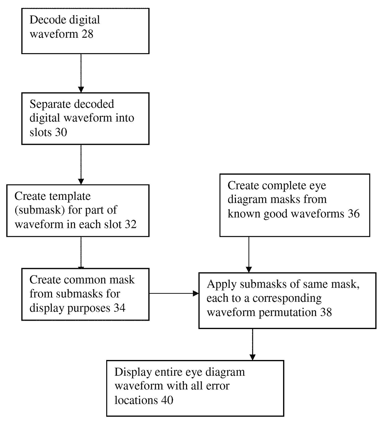
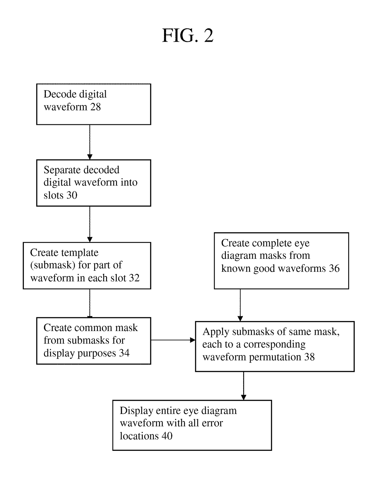
Method and arrangement for eye diagram display of errors of digital waveforms
a digital waveform and error display technology, applied in the field of automatic test equipment, can solve the problems of ringing (reflection), electrical noise, intermittent glitches, and limited commercial video test instrumentation capability, and achieve the effects of reducing overlooked anomalies, simple one-click eye mask creation, and improving eye diagram processing efficiency
- Summary
- Abstract
- Description
- Claims
- Application Information
AI Technical Summary
Benefits of technology
Problems solved by technology
Method used
Image

Examples
Embodiment Construction
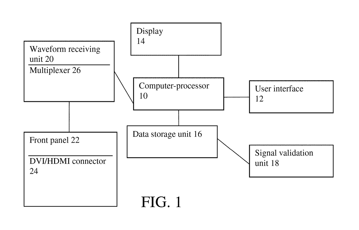
[0022]Initially, an arrangement in accordance with the invention may include whatever structure is necessary for an automated test equipment to be configured to test electronic signals generated by equipment under test (also referred to as a unit under test UUT) including, but not limited to, simultaneous complex signals. Automated test equipment, or automated test systems, arrangements or devices, is known to those skilled in the art to which this invention pertains, and the invention is equally applicable to and may be incorporated into any number of different automated test equipment. Thus, although structure to enable functionality and operability of the invention is described herein, alternative or additional structure may be used, which structure is disclosed in any number of U.S. patents that disclose automated test equipment, including those mentioned herein. Techniques disclosed herein should not therefore be considered to be limited to any particular automated test equipme...
PUM
 Abstract
Description
Claims
Application Information