Device for the lateral fitting and removal of a compressor barrel

a compressor barrel and lateral mounting technology, which is applied in the direction of machines/engines, manufacturing tools, liquid fuel engines, etc., can solve the problem that the above-described mounting devices cannot be used

Inactive Publication Date: 2014-03-25
MAN ENERGY SOLUTIONS SA
View PDF40 Cites 12 Cited by
  • Summary
  • Abstract
  • Description
  • Claims
  • Application Information

AI Technical Summary

Benefits of technology

[0011]With the aid of the supporting arm supported on the compressor casing and the supporting device connected with the bearing block, the compressor barrel can be maintained in equilibrium from one side, even if the rotor is not yet held or is no longer held on the other side in a radial ball bearing. This is advantageous especially when lateral guide rails for the mounting device cannot be mounted due to the horizontal position of the suction connection and the pressure connection on the compressor casing, and when, on the drive side of the turbocompressor, accessibility is limited by the structural design of the base forged onto the compressor casing.

Problems solved by technology

The above-described mounting devices cannot be used when the compressor barrel must be pulled incompletely, that is, without the drive-side bearing.

Method used


Image

  • Device for the lateral fitting and removal of a compressor barrel
  • Device for the lateral fitting and removal of a compressor barrel

Examples


Embodiment Construction

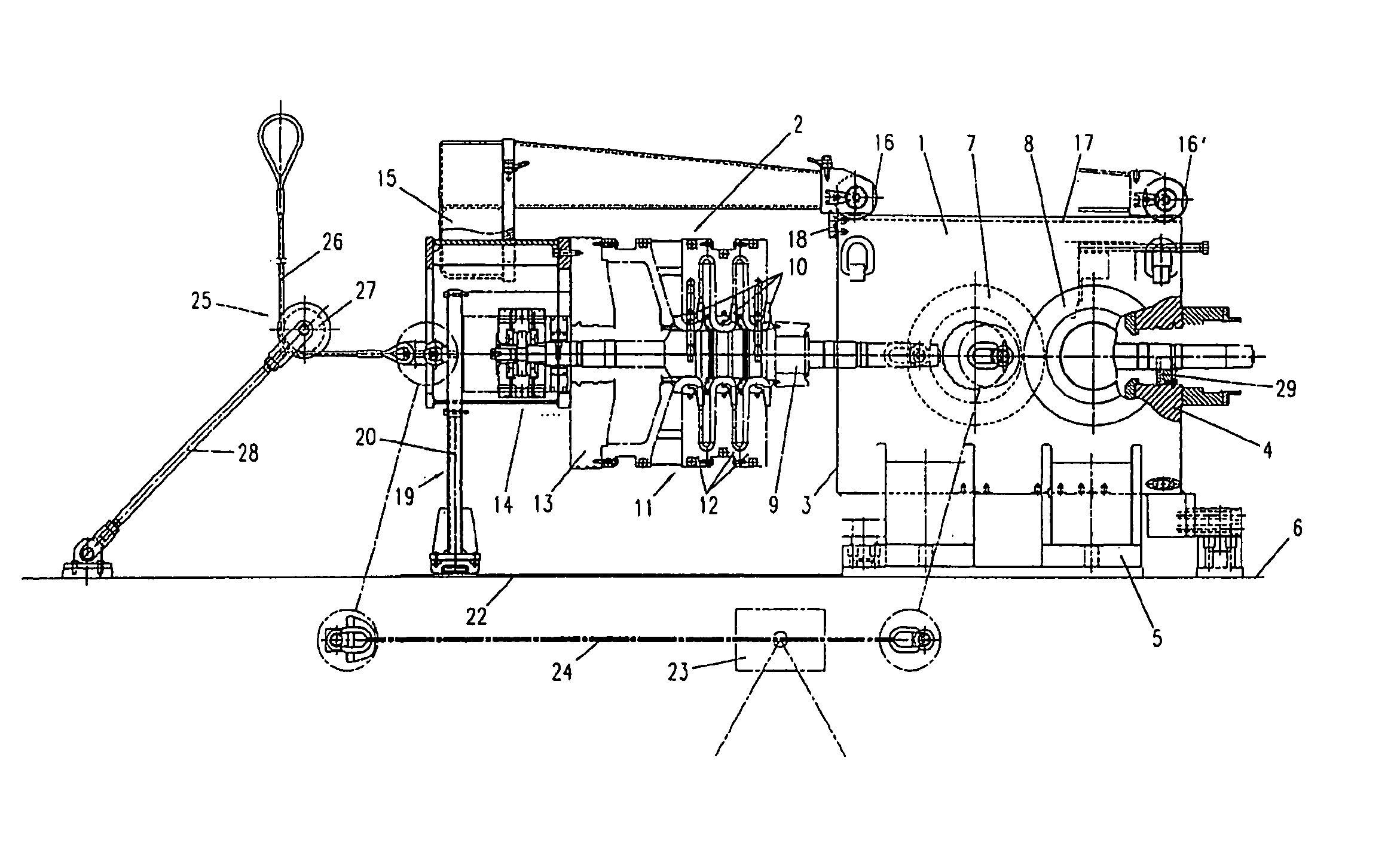
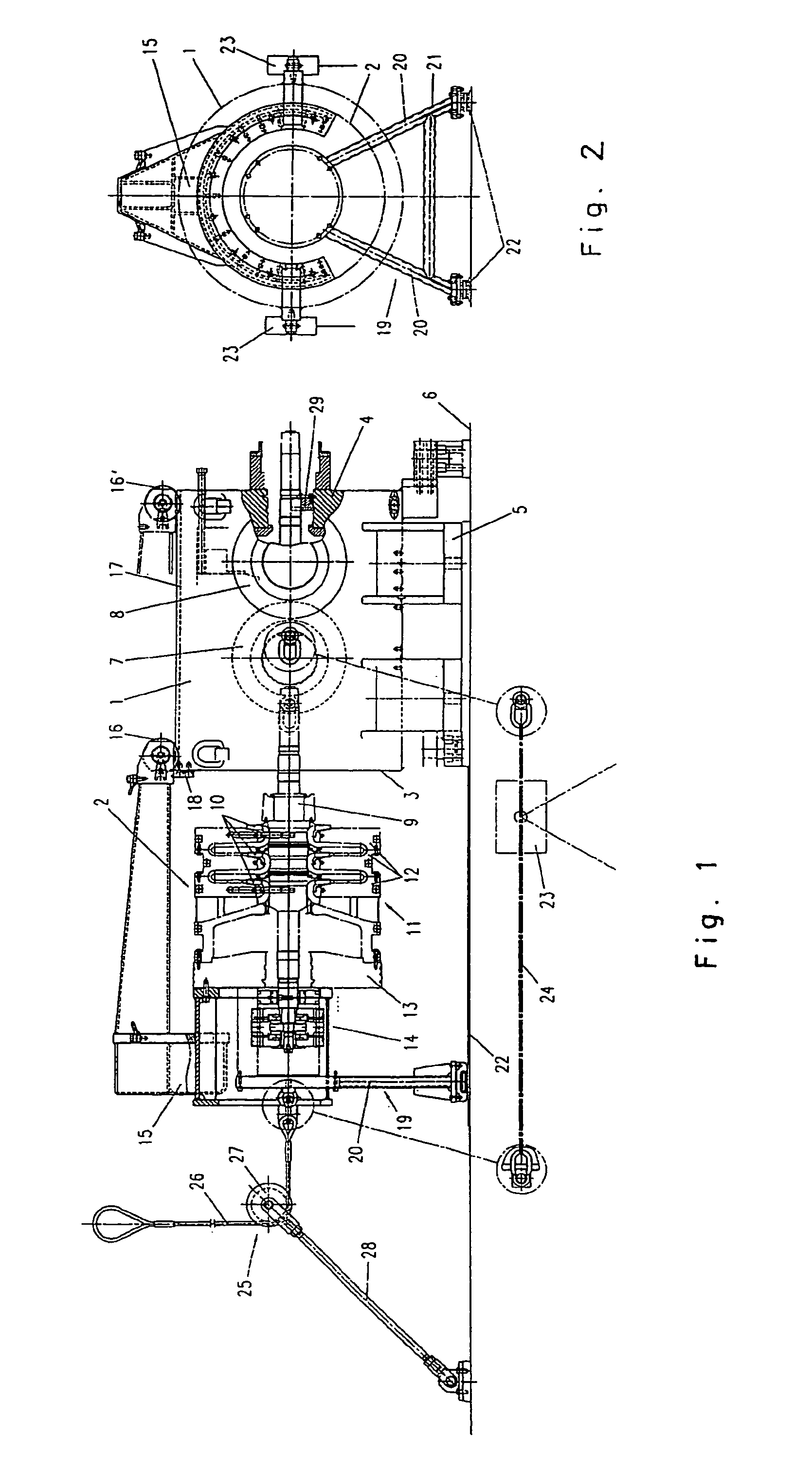
[0014]The drawings show a multistage turbocompressor with a vertically split casing 1 in a state in which the compressor barrel 2 is located outside the casing 1 immediately before mounting or immediately after dismounting.

[0015]The casing 1 of the turbocompressor has a vertical joint 3 and is unilaterally closed by a forged base 4 on one side. The compressor drive (not shown) is provided on this side of the turbocompressor. The base 4 holds a bearing for supporting the rotor 9, which will be described later. The casing 1 has casing feet 5 by which it rests on a base frame 6. A suction connection 7 and a pressure connection 8 are connected to the casing 1. In the illustrated embodiment, the two connections 7, 8 are located in the horizontal center plane of the casing 1. Depending on requirements, the two connections 7, 8 can also be arranged in the lower two thirds of the casing circumference in a position between the 2 o'clock position and the 10 o'clock position.

[0016]The compress...


PUM

PropertyMeasurementUnit
displacementaaaaaaaaaa
gas pressuresaaaaaaaaaa
equilibriumaaaaaaaaaa

Abstract

Apparatus for lateral fitting and removing of a compressor barrel into and out of a casing of a turbocompressor, the barrel having an inner core section with split disks which are bolted together coaxially, a cap rotatably mounted on a bearing block, and a rotor, wherein the disks are bolted to the cap and the rotor, and wherein the casing is vertically split and has a suction connection and a pressure connection. A support arm has a proximal end which can be releasably connected to the bearing block and a distal end which extends beyond the rotor and is displaceably supported on the casing when the proximal end is connected to the bearing block. A support device can be releasably mounted to the bearing block oppositely from the support arm, the supporting device being movable laterally on a guide to move the barrel into and out of the casing.

Description

CROSS-REFERENCE TO RELATED APPLICATIONS[0001]This is a U.S. national stage of International Application No. PCT / EP2006 / 010256, filed on 25 Oct. 2006. Priority is claimed on German Application No. 10 2005 052 077.4, filed on 28 Oct. 2005.BACKGROUND OF THE INVENTION[0002]1. Field of the Invention[0003]The invention concerns a device for the lateral mounting and dismounting of a compressor barrel of a turbocompressor into or out of a casing, which is vertically split, with wherein the barrel has an inner core section with split disks which are bolted together coaxially on a longitudinal axis, a cap rotatably mounted on a bearing block, and a rotor, wherein the disks are bolted to the cap and the rotor.[0004]2. Description of the Related Art[0005]The invention concerns a device for the lateral mounting and dismounting of a compressor barrel of a turbocompressor into or out of a casing, which is vertically split, with the features of the introductory clause of claim 1.[0006]Turbocompress...

Claims


Application Information

Patent Timeline
Patent Type & Authority Patents(United States)
IPC IPC(8): B21K25/00
CPCF01D25/285B23P19/022F04D17/125F04D29/624Y10T29/4932Y10T29/53Y10T29/53961
Inventor ZIEKOW, CHRISTIANMICHLIGK, THOMAS
Owner MAN ENERGY SOLUTIONS SA
Why Eureka
Try Eureka