Quiet muffler

a quiet and muffler technology, applied in the field of improvement, can solve the problems of increasing the cost of manufacturing known exhaust systems, affecting the quality of mufflers, and a large portion of manufacturing costs, so as to reduce the noise of mufflers, improve sound attenuation, and reduce noise. the effect of mufflers

Inactive Publication Date: 2014-03-25
CATALYTIC COMBUSTION CORP
View PDF8 Cites 2 Cited by
  • Summary
  • Abstract
  • Description
  • Claims
  • Application Information

AI Technical Summary

Benefits of technology

[0007]The present invention is directed to reduced noise muffler for use with an exhaust system wherein the shape and configuration of the inlet tubes and the exhaust pipe create flow patterns of the exhaust gases within a hollow shell that improve sound attenuation, thereby lowering the noise of the muffler and improving sound quality. It has also been found that by removing the baffles, transfer tubes, and multiple expansion chambers, the size of the expansion chamber can be maximized for the given muffler size. A larger expansion chamber has been found to be more effective at reducing the higher frequency noise, lowering the tone, and improving the sound quality. It has also been found that by adding perforations and closing off the ends of the inlet tubes, the exhaust pressure pulse is reduced or diffused through the perforations, further reducing the noise. The disclosed muffler also reduces back pressure and improves engine performance. Notably, the claimed reduced noise muffler does not include transfer tubes, baffles, or multiple expansion chambers as are typical in known mufflers.
[0012]In one embodiment of the claimed invention, the muffler is devoid of baffles, transfer tubes, and multiple expansion chambers to maximize the size of a single expansion chamber within the hollow shell member. In this and other embodiments, the shape and configuration of the first and second inlet tubes and the exhaust pipe may create flow patterns for the exhaust gases within the hollow shell that improve sound attenuation, thereby lowering the noise of the muffler and improving sound quality.
[0013]In another embodiment, the reduced noise muffler of the present invention may comprise: a hollow shell member having a first end, a second end, an inlet opening, and an outlet opening. The muffler further includes an inlet tube for receiving exhaust gasses, the inlet tube passing through the inlet opening and having a first linear portion, a second linear portion and a radiused bend located between the first and second linear portions. In at least one embodiment, the first linear portion of inlet tube is positioned within the inlet opening, meaning some of the first linear portion is disposed within the shell member and some of the first linear portion is disposed outside of the shell member, while the second linear portion and the radiused bend are positioned entirely within the hollow shell member. The muffler also includes an exhaust pipe to permit the exhaust gasses to exit the hollow shell member; wherein the muffler is devoid of baffles, transfer tubes, and multiple expansion chambers to maximize the size of a single expansion chamber within the hollow shell member.

Problems solved by technology

These known exhaust systems are expensive to manufacture due to the complexity of the systems and particularly the complexity of the muffler.
This expense is further increased since exhaust systems are typically tailored for individual off-road engine designs, which vary considerably between applications and manufacturers.
Consequently, for many off-road applications the exhaust system may account for a large portion of the total manufacturing expense.

Method used


Image

  • Quiet muffler
  • Quiet muffler
  • Quiet muffler

Examples


Embodiment Construction

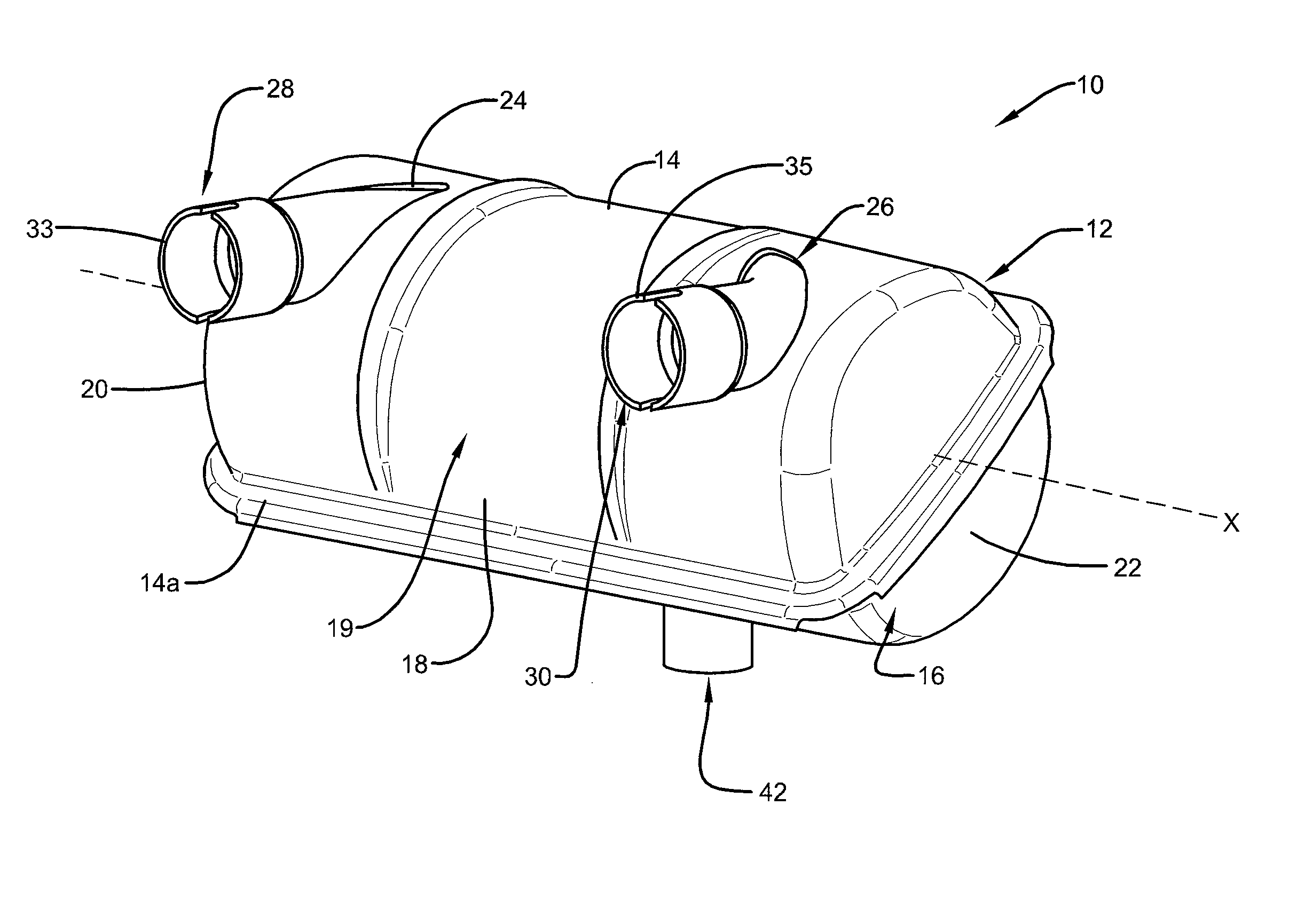
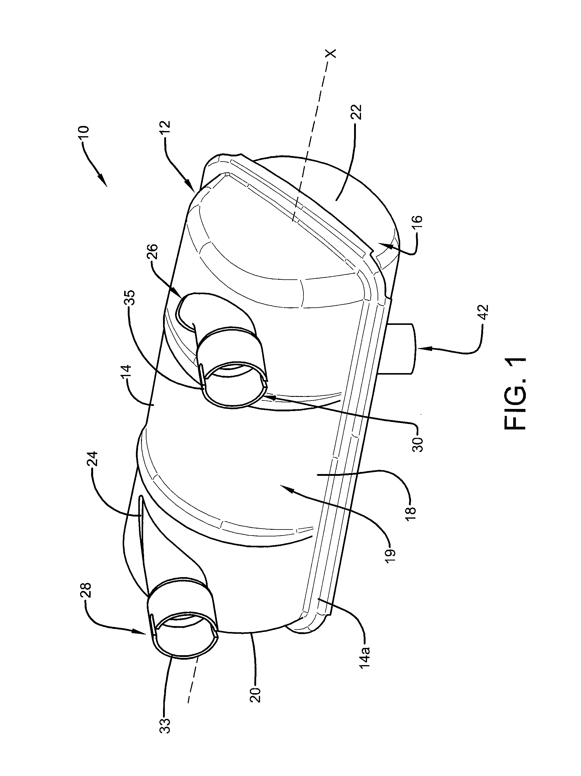
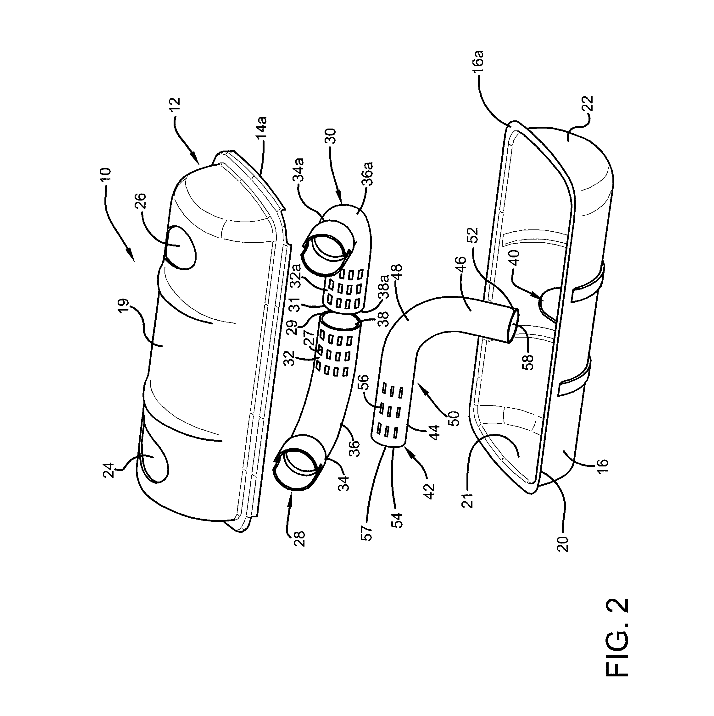
[0021]Referring now to FIGS. 1 and 2, an exhaust system is shown, generally indicated by the numeral 10. Exhaust system 10 includes a muffler 12 formed from a first concave shell member 14 and a second concave shell member 16. In one embodiment, the first shell member 14 may be symmetrical to the second shell member 16. In other embodiments, the first shell member 14 is not symmetrical to the second shall member 16. The first and second concave shell members 14 and 16 may be stamp formed by means well known in the art. In the embodiment, where the shell members 14 and 16 are symmetrical, the shell members may be substantially the same shape and size and, in some embodiments, can be stamp formed on a single dye.

[0022]The first and second shell members 14 and 16 have opposing rims 14a and 16a, respectively, which are congruent or otherwise mate and engage to form a hollow shell 18 and defining a substantially hollow expansion 19 chamber within hollow shell 18. The hollow shell 18 has ...


PUM


Abstract

An exhaust system includes a muffler, an inlet pipe, and an exhaust pipe. The muffler includes an inlet hole adapted to receive the inlet pipe and an outlet hole to receive the exhaust pipe. The inlet pipe has a first and second linear portions extending from a radiused portion, the first and second linear portions being generally perpendicular to one another. The radiused portion and the first linear portion of the inlet pipe are positioned within the muffler. Portions of the inlet pipe and exhaust pipe located within the muffler may optionally include perforations and be closed off.

Description

CROSS REFERENCE TO RELATED APPLICATIONS[0001]This application claims the benefit of U.S. provisional patent application Ser. No. 61 / 577,826 entitled “Quiet Muffler,” filed Dec. 20, 2011, which is incorporated by reference in its entirety.FIELD OF THE INVENTION[0002]This disclosure relates to an improved exhaust system and muffler. More particularly, certain embodiments of this disclosure relate to an exhaust system including a muffler that is devoid of baffles, transfer tubes, and multiple expansion chambers.BACKGROUND OF THE INVENTION[0003]Internal combustion engines are used to power a wide array of “off-road” applications, such as lawn mowers, chainsaws and leaf blowers. Exhaust systems are provided for these engines to guide waste gases away from the engine. These systems typically direct waste gases through one or more inlet tubes to a muffler, which silences the noise of the escaping exhaust gases before they are expelled from one or more outlets. Reduction of the noise genera...

Claims


Application Information

Patent Timeline
Patent Type & Authority Patents(United States)
IPC IPC(8): F01N13/08
CPCF01N1/08F01N2470/18F01N13/1888F01N2470/16F01N2470/02F01N13/08
Inventor BISCHEL, RANDALL JOSEPHKING, THOMAS PHILIP
Owner CATALYTIC COMBUSTION CORP
Why Eureka
Try Eureka