Lid operation arrangement for container

a container and operation arrangement technology, applied in the field of containers, can solve the problems of reducing affecting the service life of the container, and causing the so as to prolong the general life, prevent accidental damage of the electrical components, and enhance the practice of container us

Active Publication Date: 2014-03-25
NINE STARS GRP U S A INC
View PDF27 Cites 64 Cited by
  • Summary
  • Abstract
  • Description
  • Claims
  • Application Information

AI Technical Summary

Benefits of technology

[0016]Another advantage of the invention is to provide a lid operation arrangement for a container, wherein the lid operation arrangement can incorporate with a foot-operated container and / or the electrically-operated container.
[0017]Another advantage of the invention is to provide a lid operation arrangement for a container, wherein the lid operation arrangement will only provide a decelerating force to the lid panel when the lid panel is moved to its closed position. In other words, the lid panel can be rapidly lifted up at its opened position and can be slowly dropped down at its closed position.
[0018]Another advantage of the invention is to provide a lid operation arrangement for a container, wherein the lid operation arrangement is effectively protected within a housing against such adverse environmental factor as excess humidity, so as to prolong a general life span of the present invention.
[0019]Another advantage of the invention is to provide a lid operation arrangement for a container, wherein the opening angle of the lid panel can be configured more than 90 degrees from its closed position to its opened position for enhancing the practice use of the container.
[0020]Another object of the present invention is to provide a lid operation arrangement for a container, which is capable of lifting the lid panel in a controlled manner so as to prevent accidental damage of the electrical components of the lid operation arrangement when the lid panel is being drive to operate.
[0021]Another advantage of the invention is to provide a lid operation arrangement for a container, wherein the lid operation arrangement is located at the rear and exterior side of the container body to maximize the volume of the receiving cavity.

Problems solved by technology

In a number of situations, such as when a person is holding a lot of trash in both of his hands, it is inconvenient or difficult for the person to lift up the cover panel in that the person simply does not have spare hands to lift up the cover panel.
If the person nevertheless tries to lift up the cover panel, he risks dropping all the trash in his or her hands onto the floor.
However, they create other problems.
This may perhaps pose a certain degree of difficulty for such users as children and elderly.
Moreover, since the operation of the containers is mainly relies on stepping force on the part of the user, the paddle would break very easily especially when people apply unknowingly excessive stepping force on it.
Second, it is difficult to effectively control the actual physical motion of the cover panel, especially when the cover panel is lowered down to cover the container body.
More specifically, when the cover panel is pivotally moved to enclose the outer container body, the gravitational force (due to the weight of the cover panel) has largely been ignored by many so that the cover panel is usually subject to excessive force when being driven to enclose the outer container body.
As a result, noise will be unavoidably generated when the cover panel hits the outer container body.
In addition, the damper mechanism cannot be incorporated with the electrically-operated container.
In other words, it is a waste of electrical power of the battery for the electrically-operated container to operate the cover panel.
An excessive depression force at the foot pedal may accidentally damage the lifting rod, the damper mechanism, or even the cover panel itself.
As a result, the damper mechanism as taught by Yang is not practice in use, especially is not designed for the electrically-operated container.

Method used


Image

  • Lid operation arrangement for container
  • Lid operation arrangement for container
  • Lid operation arrangement for container

Examples


Embodiment Construction

[0054]The present invention is a modification and improvement of the previous inventions by the inventor of the present invention. The previous inventions, including U.S. Pat. Nos. 7,750,591 and 8,129,930, successfully disclose an induction actuated container, wherein the cover panel is actuated by an automatic driving arrangement to generate a decelerating and torque enhancing force to move the cover panel between the opened and closed positions in a hydraulic manner. The present invention will improve the previous inventions to enable the cover panel of the induction actuated container being actuated manually.

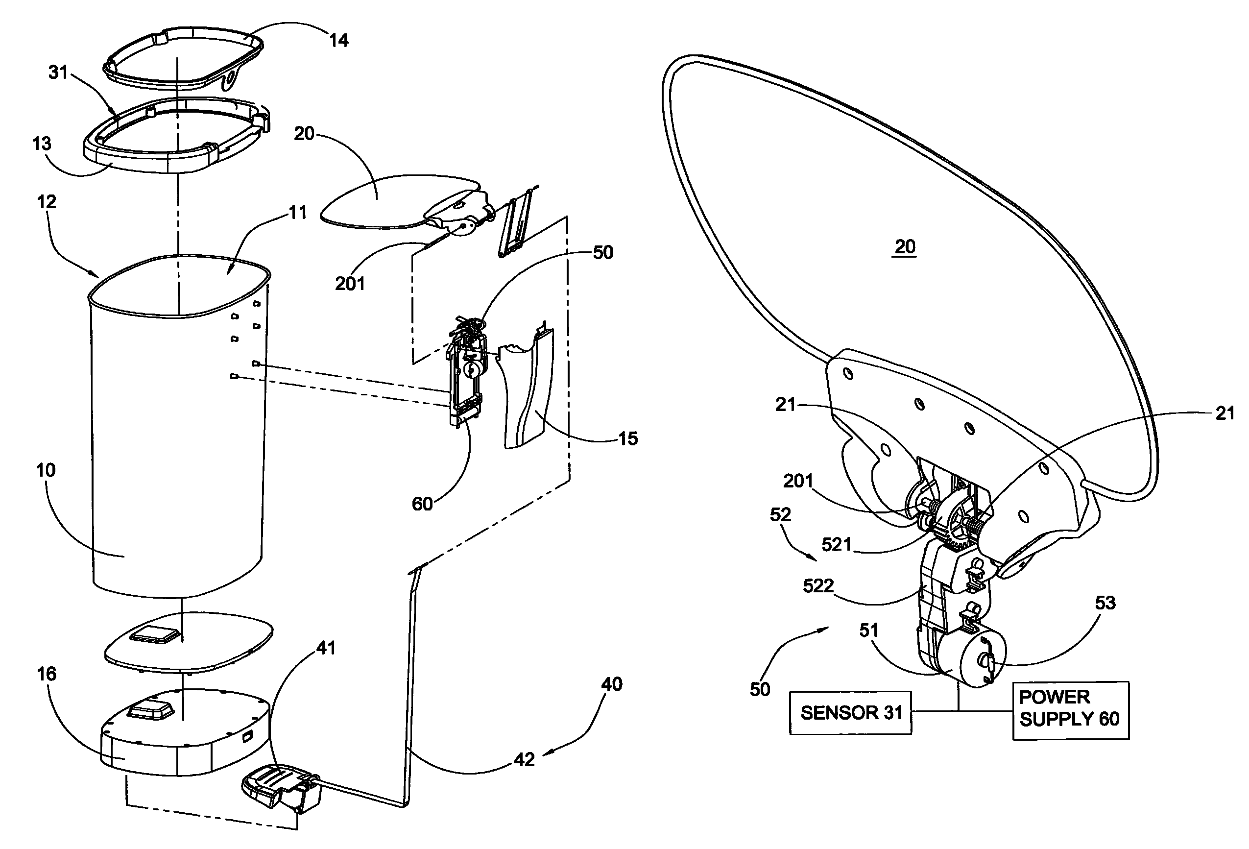
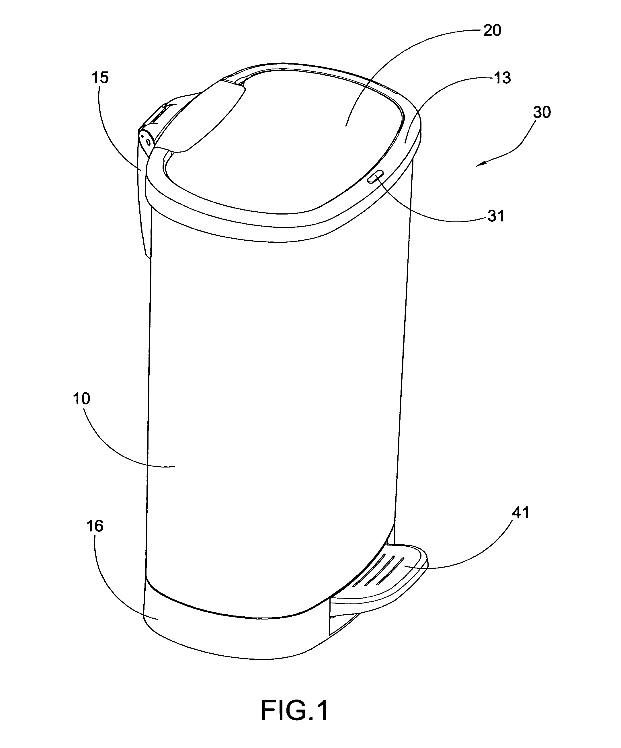
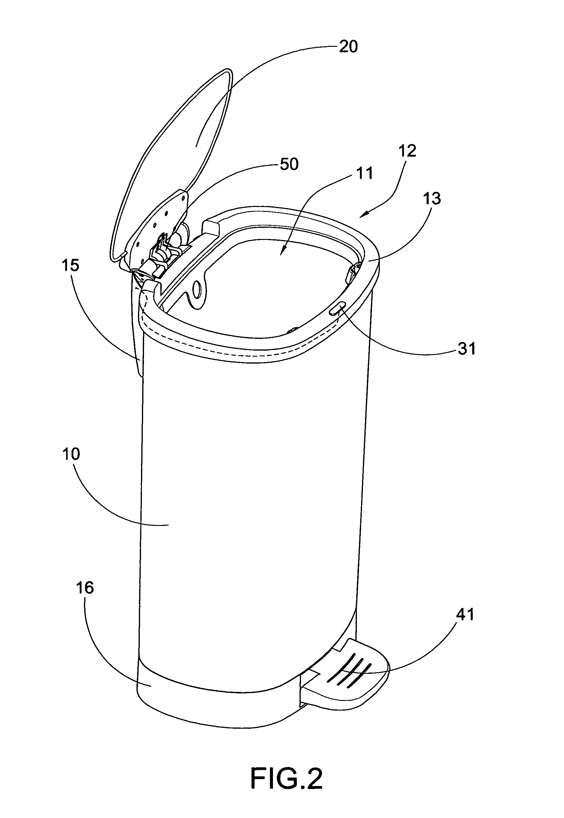
[0055]Referring to FIGS. 1 to 3 of the drawings, a container according to a first preferred embodiment of the present invention is illustrated, wherein the container comprises a container body 10, a lid panel 20, and a lid operation arrangement.

[0056]The container body 10 has a receiving cavity 11 and a top opening 12, wherein the receiving cavity 11 is utilized for storing p...


PUM


Abstract

A lid operation arrangement of a container includes an automatic operated unit for automatically operating a lid panel, a foot operated unit for manually operating the lid panel, and a motorized unit operatively linked with the automatic operated unit and the foot operated unit. When the motorized unit is activated by the automatic operated unit, the motorized unit is arranged for generating a torque enhancing force to move the lid panel from the opened position to the closed position and for generating a decelerating force to move the lid panel back to the closed position from the opened position in a hydraulic manner. After the lid panel is lifted up to the opened position by the foot operated unit, the motorized unit only generates the decelerating force to move the lid panel back to the closed position from the opened position in a hydraulic manner.

Description

BACKGROUND OF THE PRESENT INVENTION[0001]1. Field of Invention[0002]The present invention relates to a container, and more particularly to a lid operation arrangement for a container, wherein the lid panel is decelerated to cover at the cover opening of the container body in a hydraulic manner via a gear unit.[0003]2. Description of Related Arts[0004]A conventional container for storing predetermined objects, such as a trash container, usually comprises an outer container body and an inner container body disposed in the outer container body, wherein the inner container body has a receiving cavity formed therein and an opening communicated with the receiving cavity. The container further comprises a cover panel movably mounted on top of the outer container body for selectively opening and enclosing the receiving cavity for allowing the user to dispose predetermined objects into the inner container body. When the container is not in use, the receiving cavity is substantially enclosed ...

Claims


Application Information

Patent Timeline
Patent Type & Authority Patents(United States)
IPC IPC(8): B65D55/00
CPCB65F1/163B65F1/1623B65F1/1638B65F1/1607B65D55/00
Inventor WANG, XINCHEN, JIANGQUN
Owner NINE STARS GRP U S A INC
Why Eureka
Try Eureka