Liquid discharging head and method for producing the same

a liquid discharging head and liquid discharging head technology, applied in the direction of electrical transducers, printing, electric/electrostrictive/magnetostrictive devices, etc., can solve the problem of restricted selection range of channel members material, and achieve the effect of suppressing the lowering of piezoelectric properties and reducing the thermal expansion of piezoelectric elements

Active Publication Date: 2014-03-25
BROTHER KOGYO KK
View PDF12 Cites 0 Cited by
  • Summary
  • Abstract
  • Description
  • Claims
  • Application Information

AI Technical Summary

Benefits of technology

[0011]An object of the present teaching is to solve the above-described problem, and to provide an ink-jet recording head with high reliability, and to provide a method for producing such an ink-jet recording head.
[0014]Therefore, it is possible to decrease the thermal expansion of the piezoelectric element and the thermal expansion of the intermediate element as compared with a case of using the thermo-setting adhesive. Accordingly, the compressive stress applied to the piezoelectric element after the adhesion can be made small, thereby making it possible to suppress the lowering of the piezoelectric property.
[0021]Therefore, it is possible to decrease the thermal expansion of the piezoelectric element and the thermal expansion of the intermediate member (separation member) than in a case of using the thermo-setting adhesive. Accordingly, the compressive stress applied to the piezoelectric element after the adhesion can be made small, thereby making it possible to suppress the lowering of the piezoelectric property.

Problems solved by technology

In this case, however, the low-thermal expansion material has to be used as the channel member, and thus has a problem such that a range for selecting the material of channel member is restricted.
In such a case, if the ink makes contact with the room-temperature setting adhesive, a component of the curing agent contained in the adhesive elutes into the ink, which newly causes another problem.

Method used


Image

  • Liquid discharging head and method for producing the same
  • Liquid discharging head and method for producing the same
  • Liquid discharging head and method for producing the same

Examples


Embodiment Construction

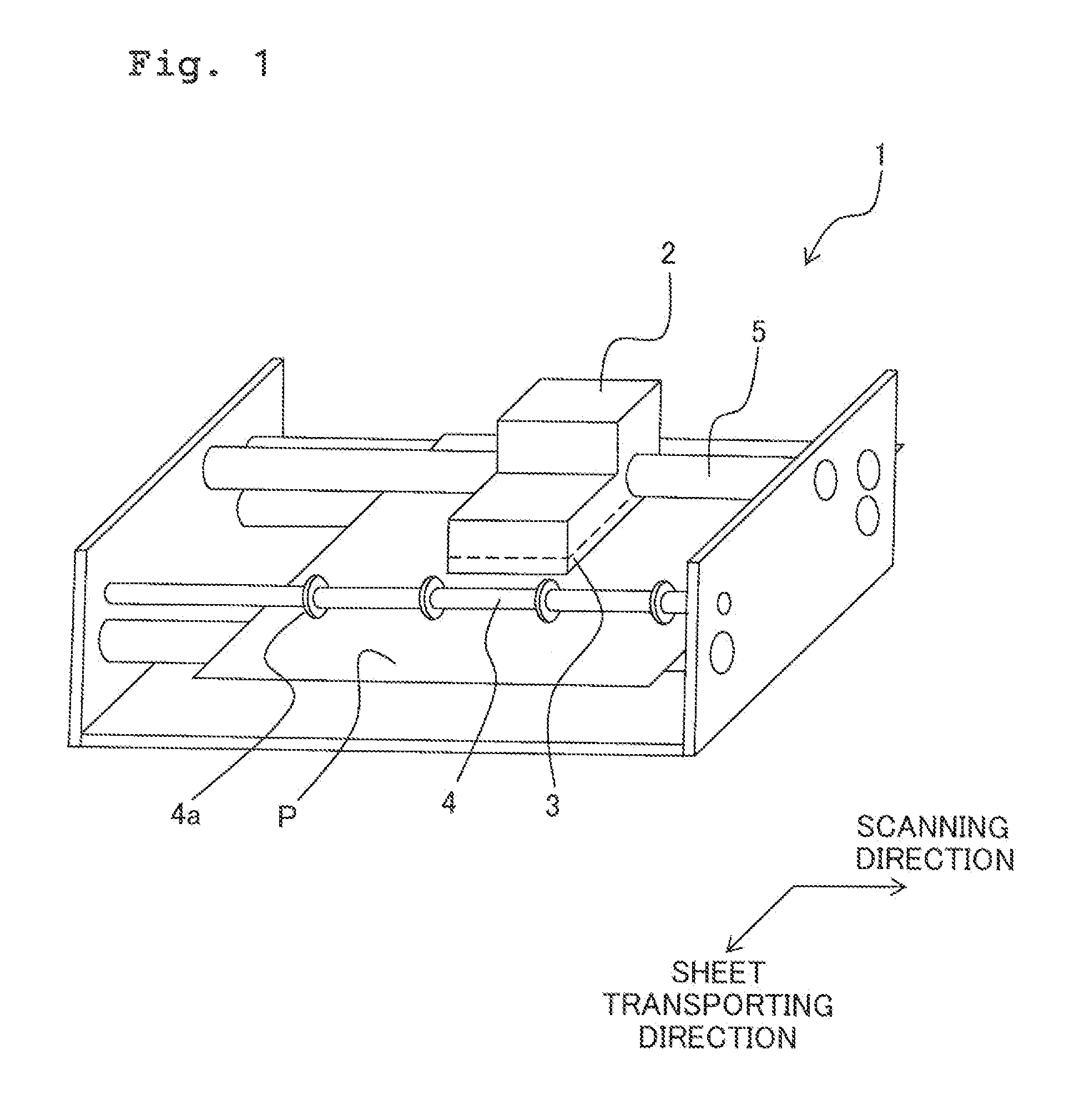
[0029]FIG. 1 is a schematic view showing the construction of a printer 1 having an ink-jet recording head 3 which is an embodiment of the present teaching. The printer 1 may be applied to a printer apparatus only having printing function, or may be applied to a printer unit included in a multi-function apparatus having a plurality of functions such as copying function, facsimile function, etc. As shown in FIG. 1, the printer 1 is provided with a carriage 2, an ink-jet recording head 3, a sheet transporting roller 4, a guide shaft 5, a platen (not shown), etc. which are arranged in an apparatus body (body) of the printer apparatus or multi-function apparatus. Note that in the following explanation, a direction in which the liquid is discharged from a nozzle is the downward direction and a direction opposite to the downward direction is the upward direction. In a case that direction(s) is defined in the drawing as necessary, an appropriate explanation therefor will be made.
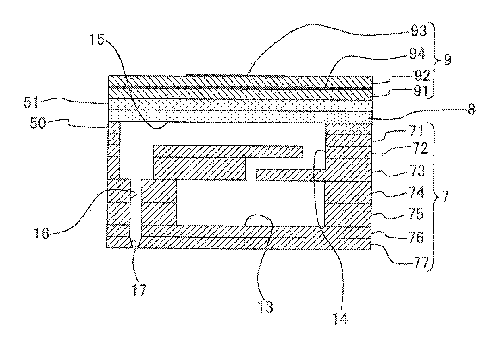
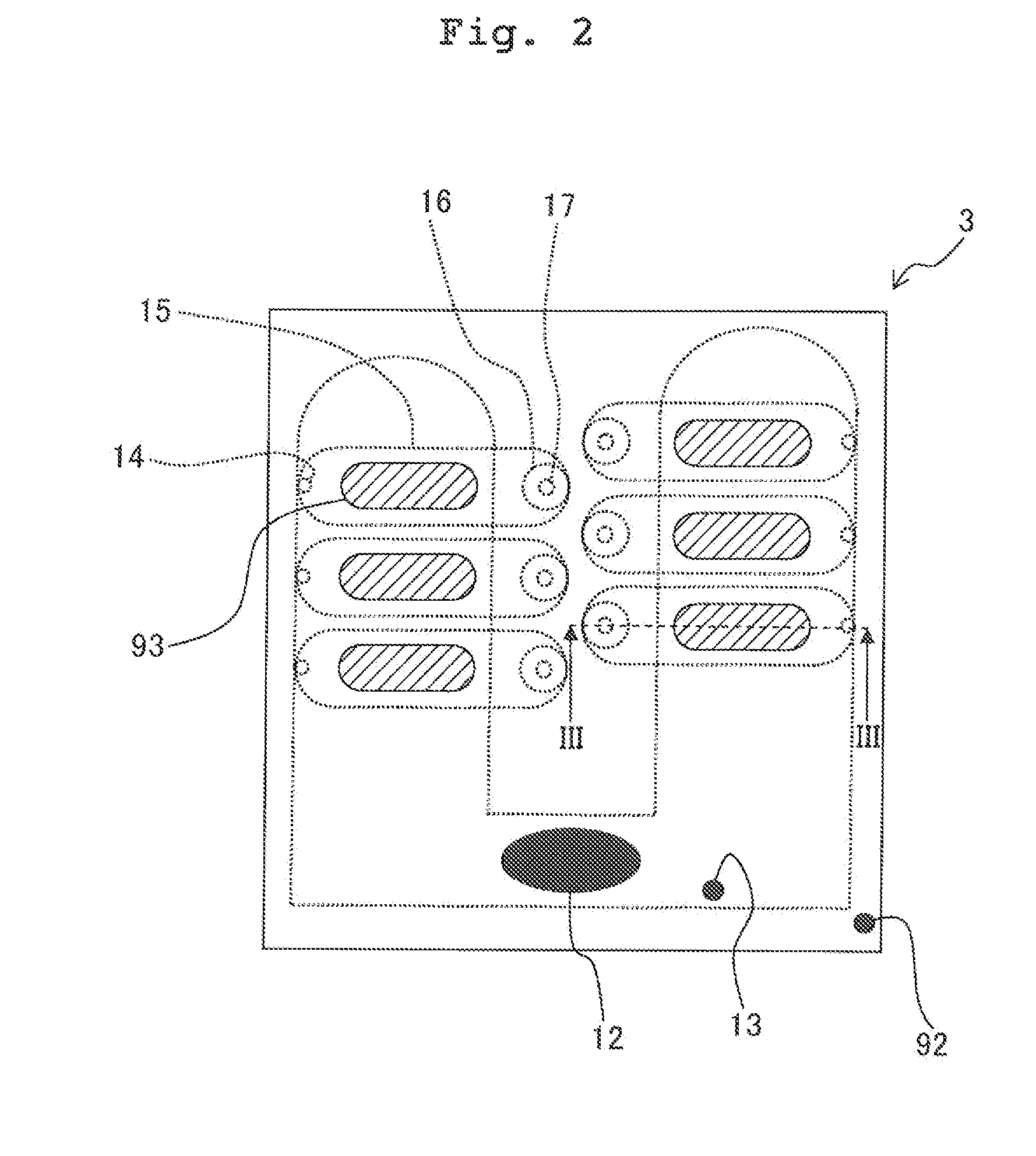
[0030]The c...


PUM

PropertyMeasurementUnit
thicknessaaaaaaaaaa
volumeaaaaaaaaaa
temperatureaaaaaaaaaa

Abstract

There is provided a liquid discharging head discharging a liquid, including: a channel unit having a liquid channel including a pressure chamber which has an opening at one surface of the channel unit; a piezoelectric element formed of a piezoelectric material; an intermediate member preventing the liquid in the pressure chamber and the piezoelectric element from making contact with each other; a first adhesive layer composed of a first adhesive and adhering the channel unit and the intermediate member, the first adhesive being a thermo-setting adhesive starting to be cured at a first temperature; and a second adhesive layer composed of a second adhesive and adhering the intermediate member and the piezoelectric element, the second adhesive starting to be cured at a second temperature lower than the first temperature.

Description

CROSS REFERENCE TO RELATED APPLICATION[0001]The present application claims priority from Japanese Patent Application No. 2010-220598 filed on Sep. 30, 2010 the disclosure of which is incorporated herein by reference in its entirety.BACKGROUND OF THE INVENTION[0002]1. Field of the Invention[0003]The present invention relates to a liquid discharging head provided on a liquid discharging apparatus such as an ink-jet recording apparatus which records a text and an image, and a method for producing the liquid discharging head.[0004]2. Description of the Related Art[0005]As an example of the liquid discharging apparatus, there is known an ink-jet recording apparatus which discharges an ink toward a recording medium to record a text, an image, etc. on the recording medium. The ink-jet recording apparatus includes an ink-jet recording head which is constructed by stacking an ink channel member having an inner space storing the ink and a piezoelectric element deformable with application of v...

Claims


Application Information

Patent Timeline
Patent Type & Authority Patents(United States)
IPC IPC(8): B41J2/045
CPCB41J2/14233Y10T29/42
Inventor HARA, KOICHIROKOBAYASHI, KAZUO
Owner BROTHER KOGYO KK
Why Eureka
Try Eureka