
Tyre-changing machine and a relative bead-breaking method

a technology of tyres and bead breaks, which is applied in the direction of tyre repairing, tyre parts, transportation and packaging, etc., can solve the problems of not solving the drawbacks and the pressure exerted by the disc against the flank of the tyre, and achieves the effect of more reliable and safer

Active Publication Date: 2014-04-01
NEXION SPA
View PDF7 Cites 2 Cited by
  • Summary
  • Abstract
  • Description
  • Claims
  • Application Information

AI Technical Summary

Benefits of technology

The present invention aims to make the process of breaking the bead of a tyre from the rim more reliable and safe, using a simple and cost-effective solution. The technical effect of the invention is to improve the efficiency and safety of heavy-duty tyre-changing machines.

Problems solved by technology

However, though the inclination of the bead-breaking disc is correctly set, the pressure exerted by the disc against the flank of the tyre does not always enable an effective detachment of the bead, especially when the bead is glued to the edge of the rim.
This difficulty is due both to the practical impossibility of setting a correct inclination of the bead-breaking disc for all wheels to be operated on, and to the fact that the pressure exerted is purely axially, and thus acts exactly in the direction of maximum resistance of the coupling between the tyre bead and the edge of the rim.
Though it improves the bead-breaking stage, this solution does not resolve the drawbacks which have been mentioned in relation to heavy-duty tyre-changing machines.

Method used


Image

  • Tyre-changing machine and a relative bead-breaking method
  • Tyre-changing machine and a relative bead-breaking method
  • Tyre-changing machine and a relative bead-breaking method

Examples


Embodiment Construction

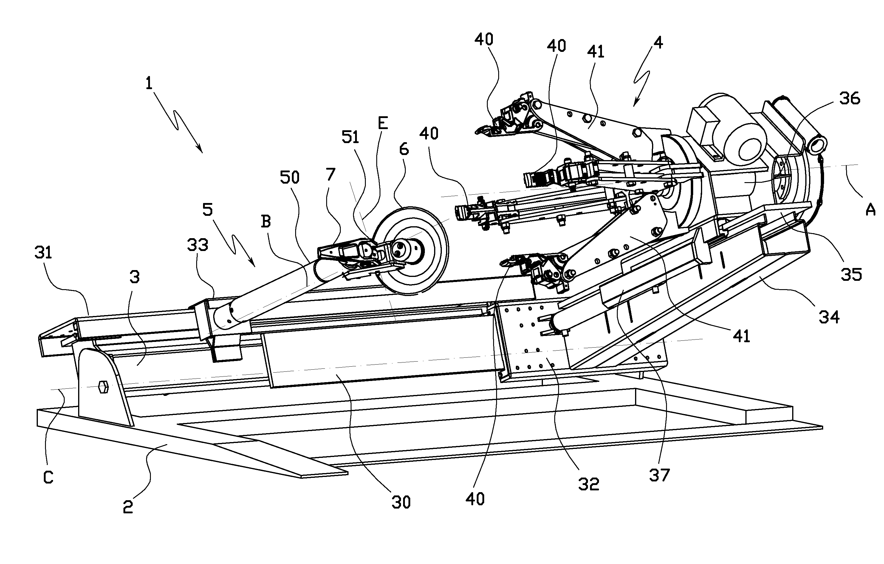
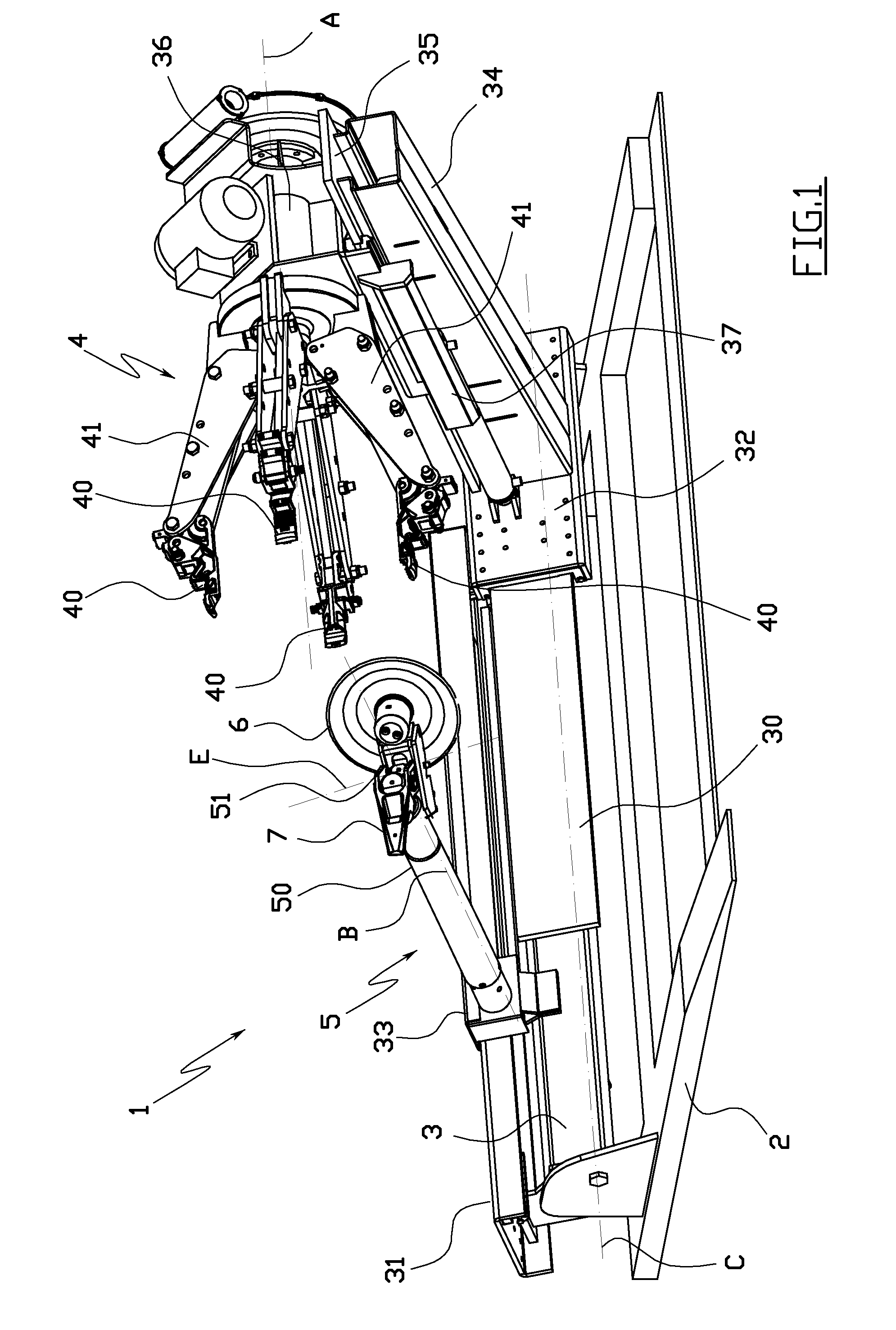
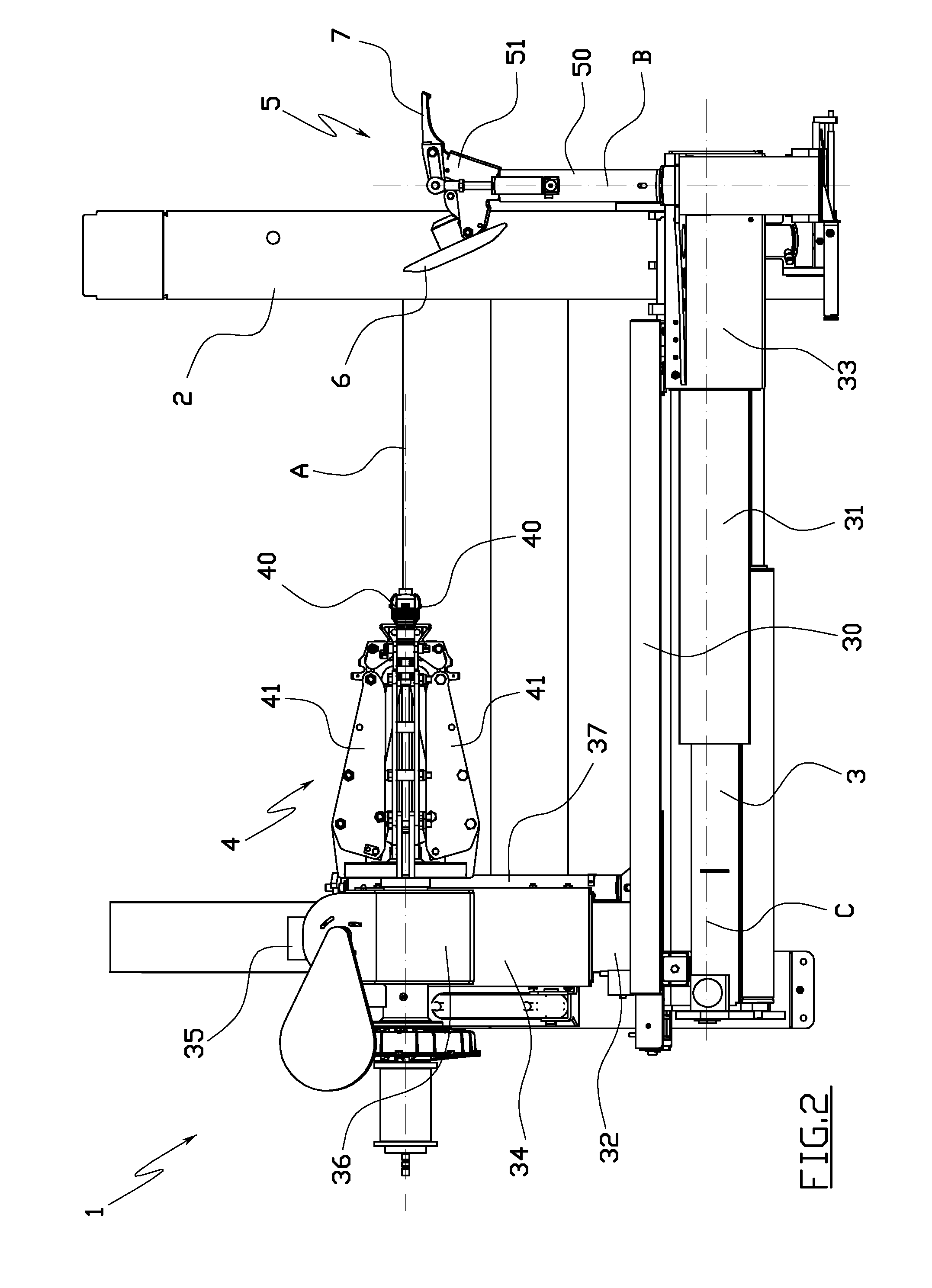
[0046]The figures illustrate a heavy-duty tyre-changing machine 1, i.e. a tyre-changing machine designed for mounting and demounting large-dimension tyres normally equipped on the wheels of heavy vehicles, such as for example trucks, lorries and agricultural tractors.

[0047]The tyre-changing machine 1 comprises a solid base 2 for resting on the ground, on which an orientable support frame 3 is mounted, which frame 3 is articulated to the base 2 on an oscillating horizontal axis C, and is associated to usual motor means (not illustrated) which vary the inclination of the frame 3 with respect to the base 2.

[0048]Two parallel straight guides, 30 and 31, are fixed on-board the orientable frame 3, on which respective slides 32 and 33 are slidably coupled.

[0049]The slides 32 and 33 are associated to means for activating, of known type, which move the slides 32 and 33 contemporaneously in a reciprocal nearing or distancing motion, in a horizontal direction which is parallel to the oscillati...


PUM

PropertyMeasurementUnit
radial distanceaaaaaaaaaa
rotationaaaaaaaaaa
sizesaaaaaaaaaa

Abstract

A tire-changing machine comprising support means (4) for a wheel, a tool-bearing arm (50) at an end of which a bead-breaking tool (6) is hinged according to a hinge axis (E) which is perpendicular to an axis (A) of the wheel, and first motorised means (32, 33) for causing a relative movement, in a parallel direction to the axis (A) of the wheel, between the support means (4) and the tool-bearing arm (50), such as to press the bead-breaking tool (6) against a flank of a tire on the wheel, characterized in that it comprises second motorised means (64), activatable independently from the first motorised means (32, 33), which second motorised means (64) are destined to rotate the bead-breaking tool (6) about the hinge axis (E) with the tool-bearing arm (50), in order to vary an inclination of the bead-breaking tool (6) with respect to the axis (A) of the wheel which is mounted on the support means (4).

Description

TECHNICAL FIELD[0001]The invention relates in general to a tyre-changing machine, and in particular a tyre-changing machine of a heavy duty type, i.e. a tyre-changing machine predisposed for operating with large-size tyres, such as those which are normally mounted on lorries or agricultural tractors.BACKGROUND ART[0002]As is known, heavy-duty tyre-changing machines generally comprise a sturdy support frame, on which two slides are mounted, provided with a reciprocal nearing and a distancing movement in a horizontal direction.[0003]A wheel-bearing chuck is mounted on a first slide, which chuck rotates about a rotation axis which is parallel to the sliding direction.[0004]A tool-bearing turret is mounted on-board the second slide, at an end of which a bead-breaking tool and a tyre-demounting tool are mounted, which are positioned on diametrically opposite sides with respect to an axis of symmetry which is perpendicular to the sliding direction.[0005]The tool-bearing turret is rotatabl...

Claims


Application Information

Patent Timeline
Patent Type & Authority Patents(United States)
IPC IPC(8): B60C25/135B60C25/138
CPCB60C25/138B60C25/0518B60C25/13B60C25/0593B60C25/0578Y10T29/49824
Inventor CORGHI, GIULIO
Owner NEXION SPA
Learn More