Pretensioning device for a safety belt

a technology of pretensioning device and safety belt, which is applied in the direction of safety belt, pedestrian/occupant safety arrangement, vehicular safety arrangement, etc., can solve the problems of affecting the movement sequence of the pretensioning device, affecting the pressure relationship of the pretensioner tube produced by the gas of a pyrotechnic gas generator, and affecting the safety of the user

Active Publication Date: 2014-04-01
AUTOLIV DEV AB
View PDF64 Cites 3 Cited by
  • Summary
  • Abstract
  • Description
  • Claims
  • Application Information

AI Technical Summary

Benefits of technology

[0011]The advantage of the inventive solution can be seen in that by means of the flow connection so created, the pressure from the pressure area can be reduced, even with an inertia body resting on the front side of the piston, namely during the pretensioning movement or with a blocked pretensioning movement. The pressure is intentionally not released into the surroundings, which is the case with the known prior art, so that parts adjacent to the pretensioning device are not endangered by the released pressure.
[0019]It is further proposed that between the first and the second part an insert is provided which closes the pass-through opening. The advantage of the use of the insert can be seen in that with regard to the selection of material and the individual dimensioning it can be so designed that it is destroyed upon exceeding of a previously determined pressure difference between the pressure prevailing in the pressure area and the pressure in the space on the other side of the piston and thus enables a pressure equalization. For the case that the pass-through opening should be released at another pressure difference, only the construction of the insert must be changed or it can be exchanged for an insert of another material without the piston being otherwise changed.
[0013]The smoothest possible change of the pressure forces acting on the inertia bodies can be attained in that the recesses are dimensioned radially symmetrical and / or identical.
[0021]This abrupt tearing can also be further caused or enhanced in that the first and / or the second part exhibit a radially inward protruding collar narrowing the pass-through opening on which the insert rests. The collar acts with a pressure loading of the insert as a cutting edge which enables the tearing off of the insert by producing appropriate cutting forces in the insert.
[0015]It is also proposed that the area of the recess(es) amounts to 15-50% of the surface of the total surface of the piston front face. By means of the proposed portion of the area of the recesses of the front face it is guaranteed that the pressure decreases quickly and the inertia body nonetheless rests on a sufficient bearing surface on the front face of the piston without the danger existing that the part of the front face on which the piston rests is melted or destroyed because of the excessively high stress from the temperatures acting thereon. The portion of the surface of the recesses thereby relates to the area of the front face of the piston on which the first inertial body rests without recesses.
[0016]It is also proposed that the piston exhibits a higher surface hardness in the area of the front face compared to the other surface. The greater surface hardness of the front face prevents the deformation of the front face in the area of the bearing surface of the inertia body and keeps the recesses from being closed due to deformation of the material. The greater surface hardness can be obtained either by a surface treatment in the area of the front face or also by a specific softening of the surface in the area of the sealing segment resting on the tube. It is thereby important that the piston meets both the requirements regarding sealing with respect to the tube as well as also regarding the force transfer across the front face.
[0017]Another preferred embodiment of the invention can be seen in the fact that the piston is constructed in at least two parts and exhibits a first part which rests on the interior wall of the tube and exhibits a second part on which the front face is placed, and the second part exhibits a greater strength than the first part. By means of the two-part design of the piston, the piston can be so constructed that it features the needed strength in the area of force transfer and simultaneously the necessary elasticity in the area of its sealing area, which is especially advantageous when the piston is guided in a curved pretensioner tube during the pretensioning process and a slight movement relative to the tube wall can be executed in the course of the curved tube.
[0018]In this case an especially cost-effective solution can be realized in that the second part of the piston is constructed from a deep-drawn part. The second part can thereby be constructed cost-effectively in mass production, whereby it is especially advantageous that the shaping of the recesses can also occur in the deep-drawing process.
[0019]It is further proposed that between the first and the second part an insert is provided which closes the pass-through opening. The advantage of the use of the insert can be seen in that with regard to the selection of material and the individual dimensioning it can be so designed that it is destroyed upon exceeding of a previously determined pressure difference between the pressure prevailing in the pressure area and the pressure in the space on the other side of the piston and thus enables a pressure equalization. For the case that the pass-through opening should be released at another pressure difference, only the construction of the insert must be changed or it can be exchanged for an insert of another material without the piston being otherwise changed.
[0020]It is further proposed that the insert be radially tensioned with a cylindrical ring extension between the first and the second part. By means of the cylindrical ring extension the insert can be fixed in the radial direction. Consequently in addition the insert can be so fixed against a deformation in the axial direction that the insert does not axially bulge in a pre-phase to release the opening, but instead tears at a predetermined pressure difference defined by the design of the insert without a deformation.
[0021]This abrupt tearing can also be further caused or enhanced in that the first and / or the second part exhibit a radially inward protruding collar narrowing the pass-through opening on which the insert rests. The collar acts with a pressure loading of the insert as a cutting edge which enables the tearing off of the insert by producing appropriate cutting forces in the insert.
[0022]In this case it is further proposed that the collar be placed on the second part and that the insert rests on the side of the second part facing the pressure area, and cuts the collar upon exceeding of a predetermined pressure in the pressure area. Since the second part exhibits a greater strength than the first part of the piston and the second part with the front face is supported on the inertia body, the pressure force acting on the insert is conveyed across the second part to the inertia body. Since the second part and the inertia body are already designed as appropriately rigid and with a stable shape because of their function to convey the pretensioning drive power, the insert thus is supported on a component assembly that is especially stable in shape and tears off when exceeding a predetermined pressure difference, without the point in time of the tearing off being dependent on a deformation of this component assembly.

Problems solved by technology

The basic problem in a pretensioning device is that the pressure relationships in a pretentioner tube produced by gas from a pyrotechnic gas generator change greatly during the pretensioning process.
Especially high pressure pressure peaks can lead to the parts of the pretensioning device being damaged or the movement sequence of the pretensioning device being impeded.
A disadvantage of the above mentioned solution is that the pressure is released outward outside the tube and thereby a hot jet or even a flash is released whereupon adjacent parts can be damaged.
In addition there is also the disadvantage that the first inertia body rests with a very high pressure on the piston during the drive movement of the piston and as a result an opening present in the piston would close.

Method used


Image

  • Pretensioning device for a safety belt
  • Pretensioning device for a safety belt
  • Pretensioning device for a safety belt

Examples


Embodiment Construction

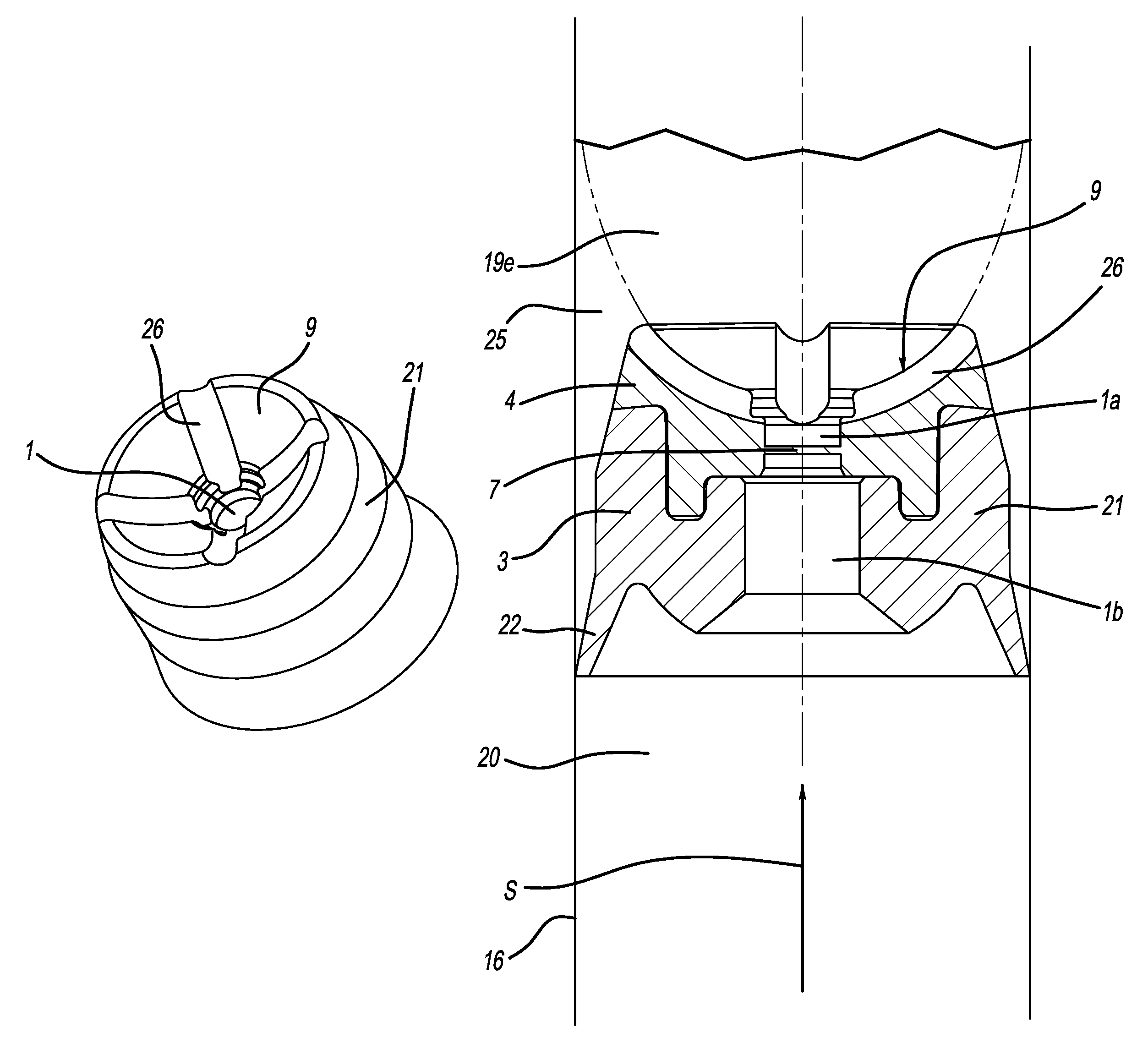
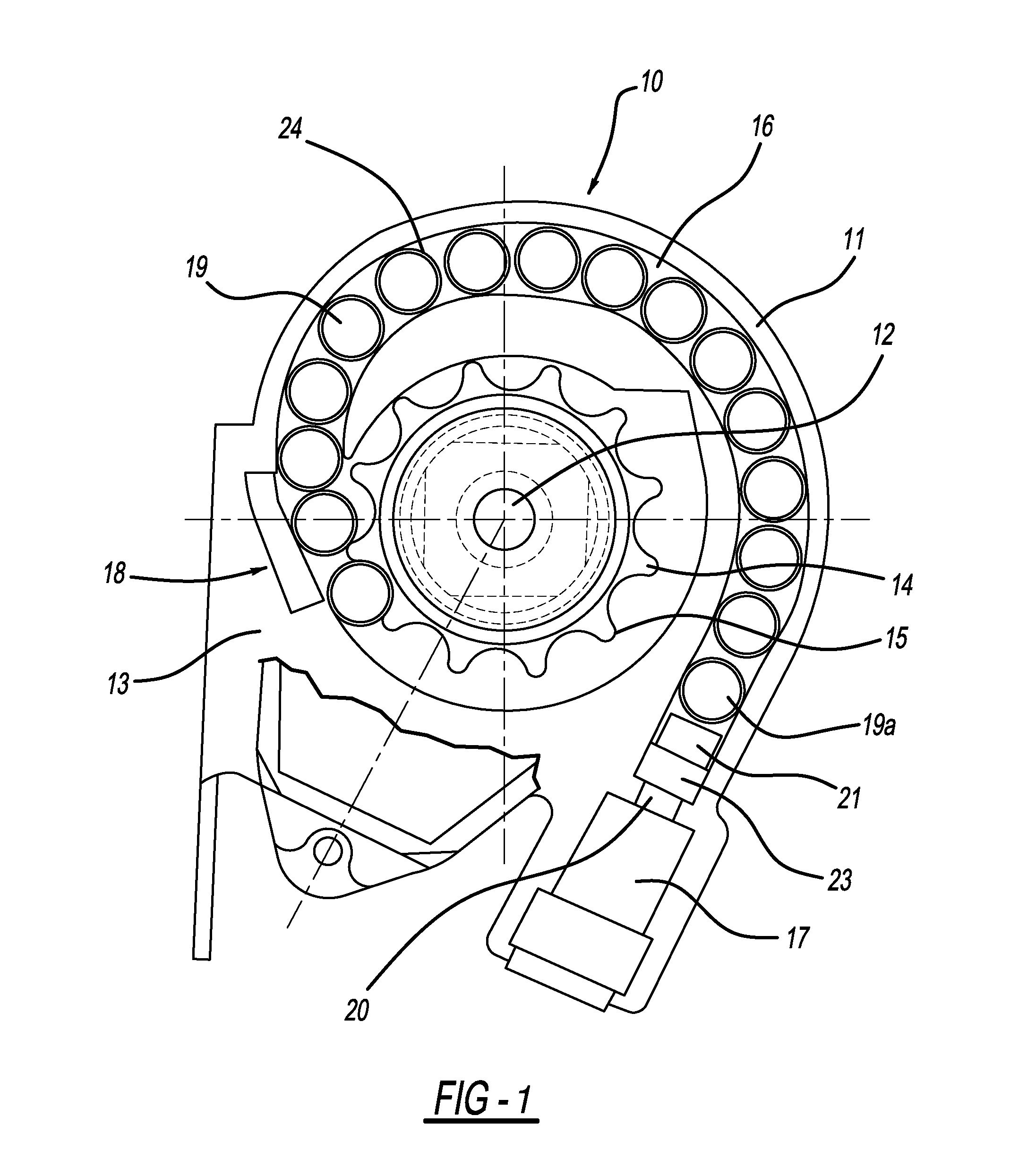
[0031]The belt retractor schematically shown in FIG. 1 comprises a housing 11 with a side leg 13, a belt coil shaft 12 placed thereon for a safety belt strap (not illustrated), and a pretensioning device 10 acting after release on the belt spool shaft 12. The pretensioning device 10 encompasses a drive wheel 14 connected in a rotationally fixed manner with the belt spool shaft 12 which, for example, features an external gearing 15, a gas generator 17, in particular pyrotechnic type, to produce a gas pressure, and a tube 16 connecting the gas generator 17 with the belt spool shaft 12 via a drive wheel 14. The tube 16 is formed by a tube wall 24 which can be part of the housing 11 or alternatively also a separate component part.

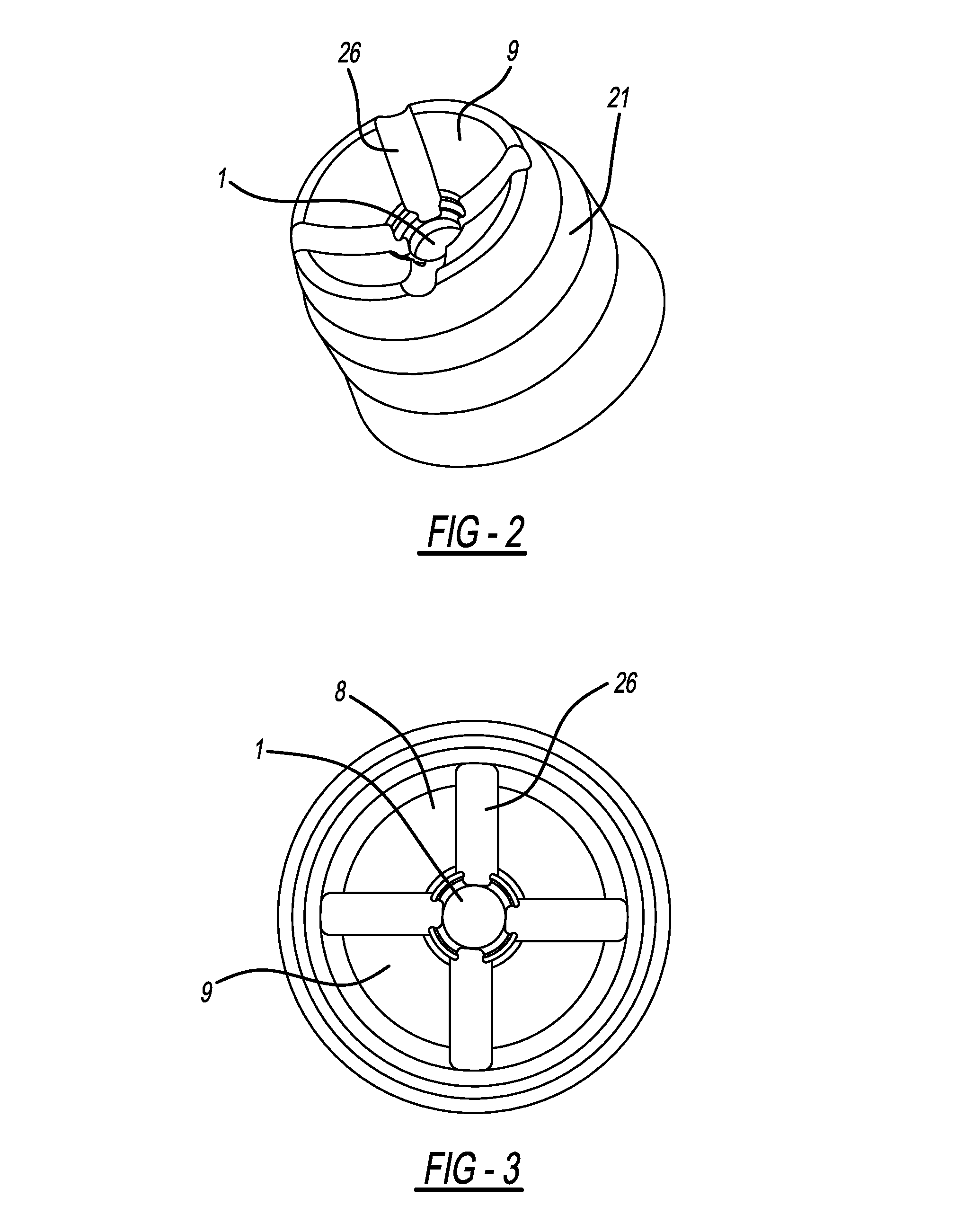
[0032]Provided in the tube 16 is a series of metallic ball-shaped inertia bodies 19 to convey the pretensioning movement caused by the gas pressure produced by the gas generator 17 to the belt spool shaft 12 via the drive wheel 14. The belt retractor is not lim...


PUM


Abstract

A pretensioning device (10) for a safety belt, of a motor vehicle, having a gas generator (17), a piston (21) guided in a tube (16), which closes a pressure area (20) in the tube (16) that is pressurized by the gas generator (17) whereupon the piston (21) is able to move in a pretensioning movement which is able to be conveyed to the safety belt by means of an inertia body (19a) resting on a front face (9) of the piston (21). The piston (21) forms a pass-through opening (1) releasable upon exceeding of a predetermined pressure and a recess (26) is provided in the front face (9) with an inertia body (19a) resting thereon, so that a flow connection is created from the pass-through opening (1) to the area (25) located behind the piston (21) in the direction of the pretensioning movement (S).

Description

CROSS-REFERENCE TO RELATED APPLICATIONS[0001]This application claims priority to German Patent Application No. 10 201 0 018 512.4, filed Apr. 27, 2010 and PCT / EP2011 / 001057, filed Mar. 3, 2011.FIELD OF THE INVENTION[0002]The invention relates to a pyrotechnic pretensioning device for a safety belt, in particular for use in a motor vehicle.BACKGROUND OF THE INVENTION[0003]The basic problem in a pretensioning device is that the pressure relationships in a pretentioner tube produced by gas from a pyrotechnic gas generator change greatly during the pretensioning process. Especially high pressure pressure peaks can lead to the parts of the pretensioning device being damaged or the movement sequence of the pretensioning device being impeded.[0004]Already known from DE 195 45 795 C1 is a pyrotechnical driving device with an overpressure safety by means of which an exceeding of a predetermined pressure is prevented in the tube of the pretensioning device. In this solution, an opening is pro...

Claims


Application Information

Patent Timeline
Patent Type & Authority Patents(United States)
IPC IPC(8): B60R22/405
CPCB60R2022/4642B60R22/4628B60R2022/4661B60R2022/4638
Inventor SCHMIDT, THOMASSCHMIDT, MARTINFISCHER, CHRISTIANPECH, MICHAELSTEINBERG, MATTHIASVOSS, TOBIAS
Owner AUTOLIV DEV AB
Why Eureka
Try Eureka