Sleeving valve type hydraulic breaking hammer

A technology of hydraulic breaker and breaker, which is used in earthmoving machines/shovels, mechanically driven excavators/dredgers, construction, etc. Large, prone to problems such as strain or stuck, achieving the effect of small throttling loss, small pressure bearing area and compact structure

Inactive Publication Date: 2016-11-16
SHANGHAI UNIV OF ENG SCI
View PDF7 Cites 3 Cited by
  • Summary
  • Abstract
  • Description
  • Claims
  • Application Information

AI Technical Summary

Problems solved by technology

[0003] (1) The structure of the column valve type breaker is generally a stepped structure, the structure is poor in manufacturability, and the throttling loss is large;
[0004] (2) The pressure-bearing area of ​​the reversing valve is generally large, which will lead to excessive pressure on the cross-section and affect its life;
[0005] (3) The reversing valve and the piston are separated, and each has its own spool. Due to the reduced size parameters of the reversing valve, the size of the reversing valve is often larger, resulting in a larger range of motion or an increase in the overall quality. is too big;
[0006] (4) The piston generally has a large return and stroke stroke, which is prone to strain or jamming;
[0007] (5) Due to the large stroke of the piston and the reversing valve, the impact frequency is reduced, which affects the working efficiency

Method used


Image

  • Sleeving valve type hydraulic breaking hammer
  • Sleeving valve type hydraulic breaking hammer
  • Sleeving valve type hydraulic breaking hammer

Examples


Embodiment 1

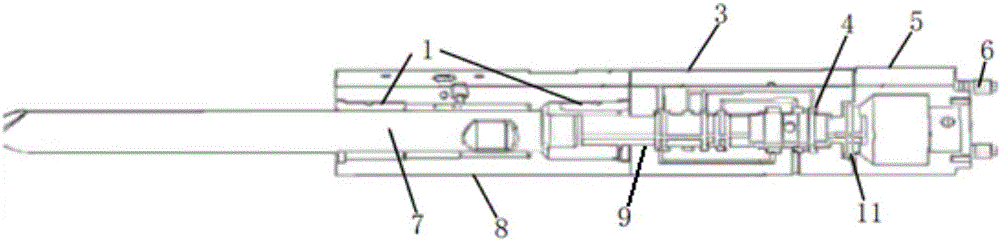
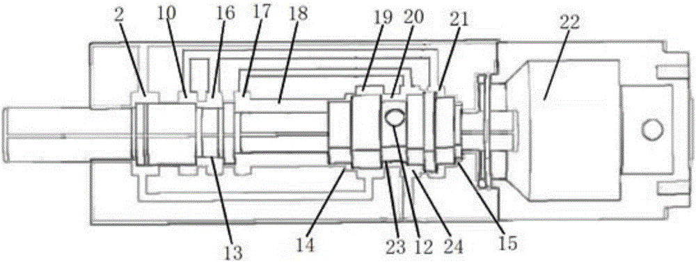
[0040] Such as Figure 1-3 A sleeve valve type hydraulic breaking hammer is shown, which includes a precursor 8, a middle cylinder 3 and a nitrogen chamber 5 arranged in sequence from front to back, and an O-shaped sealing ring 11. The inside of the front body 8 is provided with a drill rod 7 along the axial direction, and a drill rod bushing 1 is arranged between the inner wall of the front body 8 and the drill rod 7, and a device for axially limiting the drill rod 7 is also arranged in the front body 8. Rod plugging. The inside of the middle cylinder 3 is provided with a piston 9 connected to the drill rod 7, a sleeve valve 4 sleeved outside the piston 9 and adapted to the inner wall of the middle cylinder 3, and a drive piston 9 and the sleeve valve 4 along the middle cylinder. 3. A hydraulic oil circuit system with axial reciprocating movement. The inner wall of the middle cylinder body 3 is provided with a front stop surface 14 of the sleeve valve and a rear stop surfac...

Embodiment 2

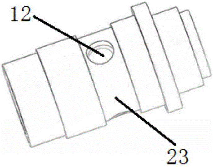
[0047] In this embodiment, five through-holes 12 communicating with the pressure-transforming chamber 18 are evenly opened on the bottom surface of the sleeve valve groove 23 , and the rest are the same as in the first embodiment.


PUM


Abstract

The invention relates to a sleeving valve type hydraulic breaking hammer. The sleeving valve type hydraulic breaking hammer comprises a front body, a middle cylinder and a nitrogen chamber which are sequentially arranged from front to back. A drill rod is arranged inside the front body in the axial direction. The middle cylinder is internally provided with a piston, a sleeving valve and a hydraulic oil path system, wherein the piston is in transmission connection with the drill rod; the sleeving valve is arranged outside the piston in a sleeving mode and matched with the inner wall of the middle cylinder; and the hydraulic oil path system drives the piston and the sleeving valve to move back and forth in the axial direction of the middle cylinder. In the working state, the piston drives the drill rod to move back and forth in the axial direction of the middle cylinder under driving of the hydraulic oil path system, and accordingly hard objects are broken. Compared with the prior art, the sleeving valve type hydraulic breaking hammer is simple in structure, the sleeving valve is directly arranged on the piston in the sleeving mode, a valve element is omitted, the structure is more compact, and structure manufacturability is good; and since the travel stroke of the sleeving valve is short, the working efficiency is remarkably improved, and the demands of engineering application can be met.

Description

technical field [0001] The invention belongs to the technical field of hydraulic breaking hammers, and relates to a sleeve valve type hydraulic breaking hammer. Background technique [0002] A hydraulic breaker is an impact tool that converts hydraulic energy into mechanical energy. The existing hydraulic breaker has a distribution valve for changing the direction of oil flow, which realizes and controls the reciprocating motion of the impact piston. The currently used column valve type breaker has the following deficiencies: [0003] (1) The structure of the column valve type breaker is generally a stepped structure, the structure is poor in manufacturability, and the throttling loss is large; [0004] (2) The pressure-bearing area of ​​the reversing valve is generally large, which will lead to excessive pressure on the cross-section and affect its life; [0005] (3) The reversing valve and the piston are separated, and each has its own spool. Due to the reduced size para...

Claims


Application Information

Patent Timeline
Patent Type & Authority Applications(China)
IPC IPC(8): E02F3/96
CPCE02F3/966
Inventor 徐子善杨国平卞贤掌
Owner SHANGHAI UNIV OF ENG SCI
Why Eureka
Try Eureka