
Liquid ejecting head, liquid ejecting unit, and liquid ejecting apparatus

a liquid ejecting unit and liquid ejecting technology, which is applied in printing, inking apparatus, other printing apparatus, etc., can solve the problems of clogging the filter, affecting and reducing the print performance of the ink-jet recording apparatus, so as to prevent the filter from becoming clogged up and improve the liquid ejecting characteristics.

Active Publication Date: 2014-04-01
SEIKO EPSON CORP
View PDF7 Cites 15 Cited by
  • Summary
  • Abstract
  • Description
  • Claims
  • Application Information

AI Technical Summary

Benefits of technology

The invention provides a liquid ejecting head that prevents filters from becoming clogged and improves liquid ejection characteristics. The liquid ejecting apparatus includes the liquid ejecting head and can eject liquid effectively. This helps to maintain optimal performance of the liquid ejection process.

Problems solved by technology

The trapped air bubbles cover the upper surface of the filter to clog it up completely, which obstructs the circulatory flow of ink.
Because the circulation of ink is hampered, the print performance of the ink-jet recording apparatus decreases.
That is, the same problem could also arise in various kinds of liquid ejecting apparatuses provided with a liquid ejecting head(s) for ejecting liquid, which is not limited to ink.

Method used


Image

  • Liquid ejecting head, liquid ejecting unit, and liquid ejecting apparatus
  • Liquid ejecting head, liquid ejecting unit, and liquid ejecting apparatus
  • Liquid ejecting head, liquid ejecting unit, and liquid ejecting apparatus

Examples


Embodiment Construction

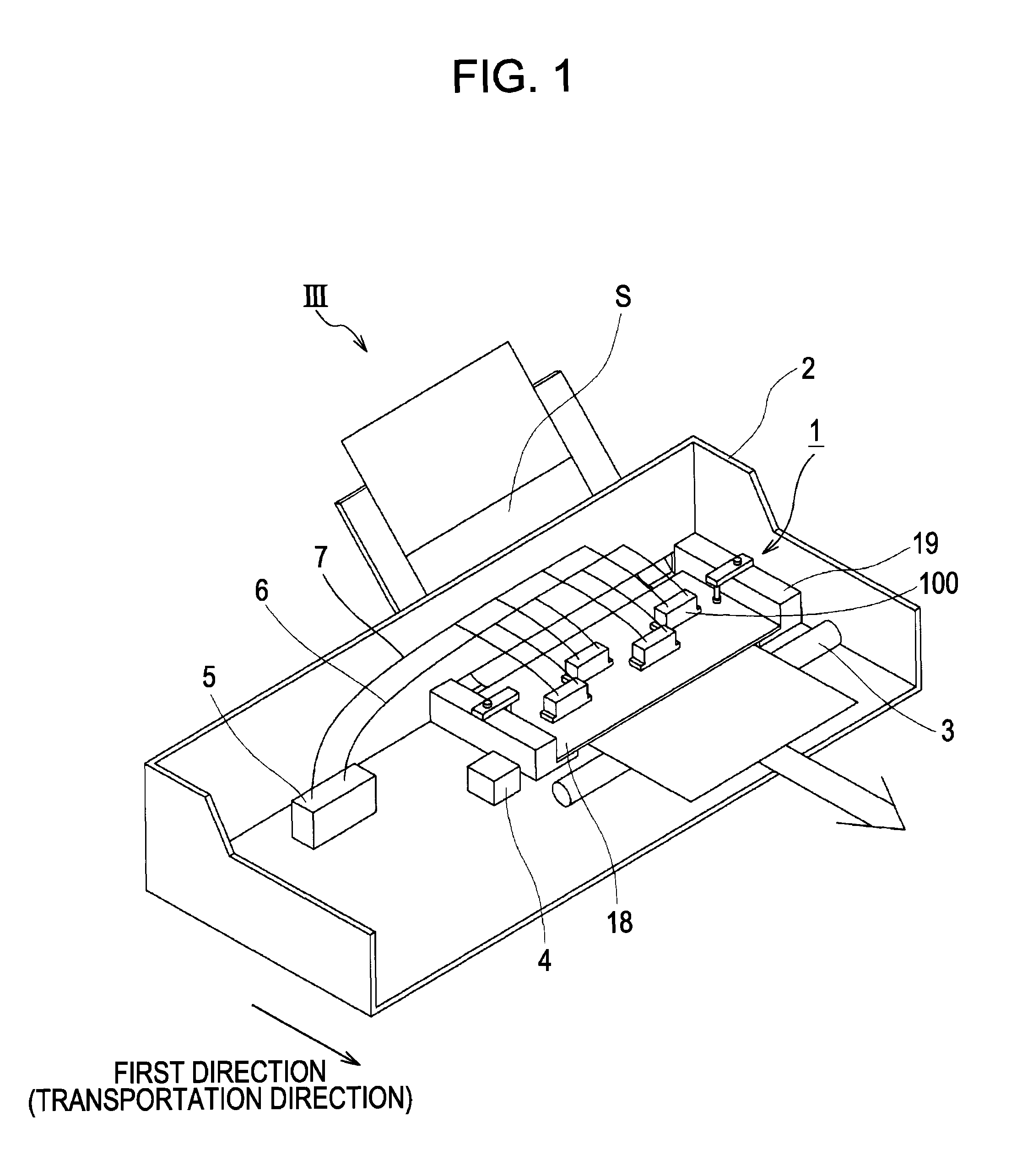
[0023]With reference to FIGS. 1 to 6, a liquid ejecting apparatus according to an aspect of the present invention will now be explained. An ink-jet recording apparatus according to the present embodiment of the invention is a so-called line ink-jet printer (recording apparatus) that is equipped with liquid ejecting heads fixed to the body of the apparatus. The apparatus prints an image on the surface of a recording target medium such as a sheet of printing paper while transporting it in the direction orthogonal to the direction of nozzle lines. An ink-jet recording apparatus III illustrated in FIG. 1 includes a head unit 1, an apparatus body 2, a paper-feed roller 3, and a control unit 4. The paper-feed roller 3 is an example of a target-moving means.

[0024]The head unit 1 includes a head group and a base plate 18. The head group is made up of a plurality of liquid ejecting heads (hereinafter referred to as “heads”) 100. In the illustrated example of FIG. 1, four heads 100 are mounte...


PUM


Abstract

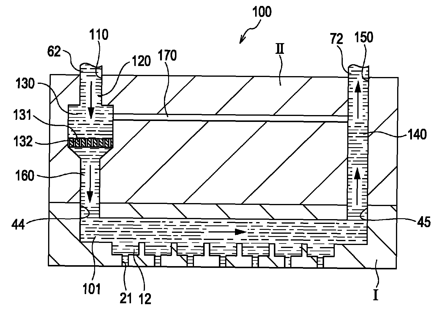
A liquid ejecting head comprising, a plurality of nozzle openings, a first flow passage, a circulation flow passage, a filter chamber, and a bypass flow passage, an inner diameter of the bypass flow passage is larger than a diameter of the hole of the filter, the inner diameter of the bypass flow passage is larger than a diameter of the nozzle opening, and a flow passage resistance of the bypass flow passage is larger than a flow passage resistance of the circulation flow passage from a branch point where the bypass flow passage branches from the supply passage to a junction point where the bypass flow passage merges into the collection passage.

Description

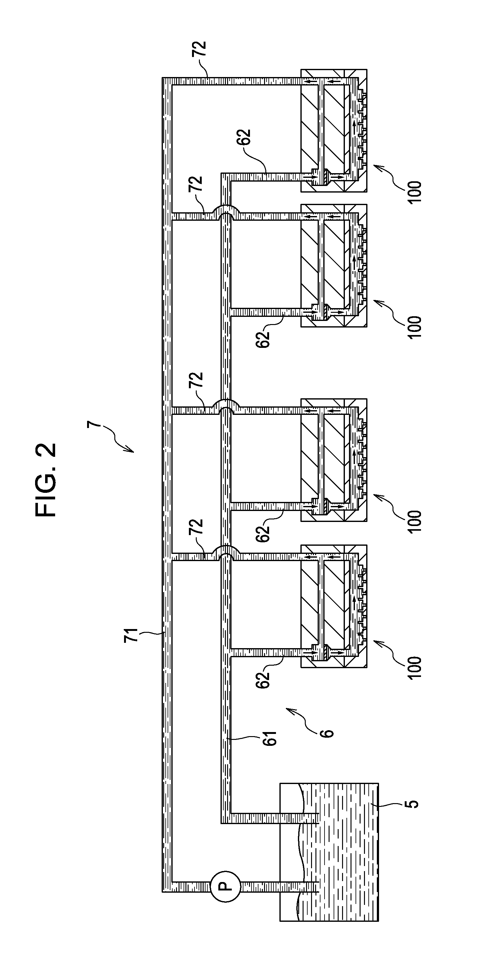
[0001]The entire disclosure of Japanese Patent Application No: 2010-081517, filed Mar. 31, 2010 are expressly incorporated by reference herein.BACKGROUND[0002]1. Technical Field[0003]The present invention relates to a liquid ejecting head, a liquid ejecting unit, and a liquid ejecting apparatus.[0004]2. Related Art[0005]A circulation-type apparatus is known in the field of an ink-jet recording apparatus, which is an example of a liquid ejecting apparatus. In a known circulation-type ink-jet recording apparatus, for example, one disclosed in JP-A-2009-23289 (in particular, refer to FIG. 3), an ink tank is provided at a distance from an ink-jet recording head. Ink flows from the ink tank to the ink-jet recording head, and then back to the ink tank in a circulatory manner.[0006]In the ink-jet recording apparatus disclosed in JP-A-2009-23289, a single tube on an outgoing channel and a single tube on a return channel are connected to the ink tank. A plurality of branch tubes is branched ...

Claims


Application Information

Patent Timeline
Patent Type & Authority Patents(United States)
IPC IPC(8): B41J2/18
CPCB41J29/02B41J2/18B41J2/14233B41J2202/11
Inventor UEZAWA, HARUHISA
Owner SEIKO EPSON CORP
Learn More