Gear screw adjuster

a technology of screw adjuster and screw head, which is applied in the direction of instruments, lighting and heating apparatus, lighting support devices, etc., to achieve the effects of improving seal, cost-effectiveness, and convenient installation

Active Publication Date: 2014-04-01
BURTON TECH
View PDF14 Cites 2 Cited by
  • Summary
  • Abstract
  • Description
  • Claims
  • Application Information

AI Technical Summary

Benefits of technology

[0006]The present invention provides a gear screw adjuster assembly that is cost-effective, easily installed in the lamp where it is securely retained, provides an improved seal and reduces torque screw variation, allows for adjustment in multiple directions with the use of a simple and inexpensive component that also provides a clutching feature, and which solves the problems raised or not solved by existing designs. In one embodiment an O-ring creates a complete radial seal between the neck of the gear screw and the O-ring, providing improved torque control and a robust air-tight seal.
[0008]The grommet may provide multiple functions in addition to engaging the reflector. It can also provide for movement in multiple directions, including angular pivoting of the reflector and side-to-side movement by movement of the grommet within the reflector opening. The grommet may also provide a clutching feature, whereby the gear screw will “clutch,” or disengage to stop movement of the reflector, when reaching a certain point on the threads of the gear screw to prevent over-travel and damage to the assembly.

Problems solved by technology

However, the adjuster of Makita requires multiple steps for assembly into the headlamp housing, where the self-locking nut must be mounted to the reflector bracket and the adjusting rod then threaded into the nut.

Method used


Image

  • Gear screw adjuster
  • Gear screw adjuster
  • Gear screw adjuster

Examples


Embodiment Construction

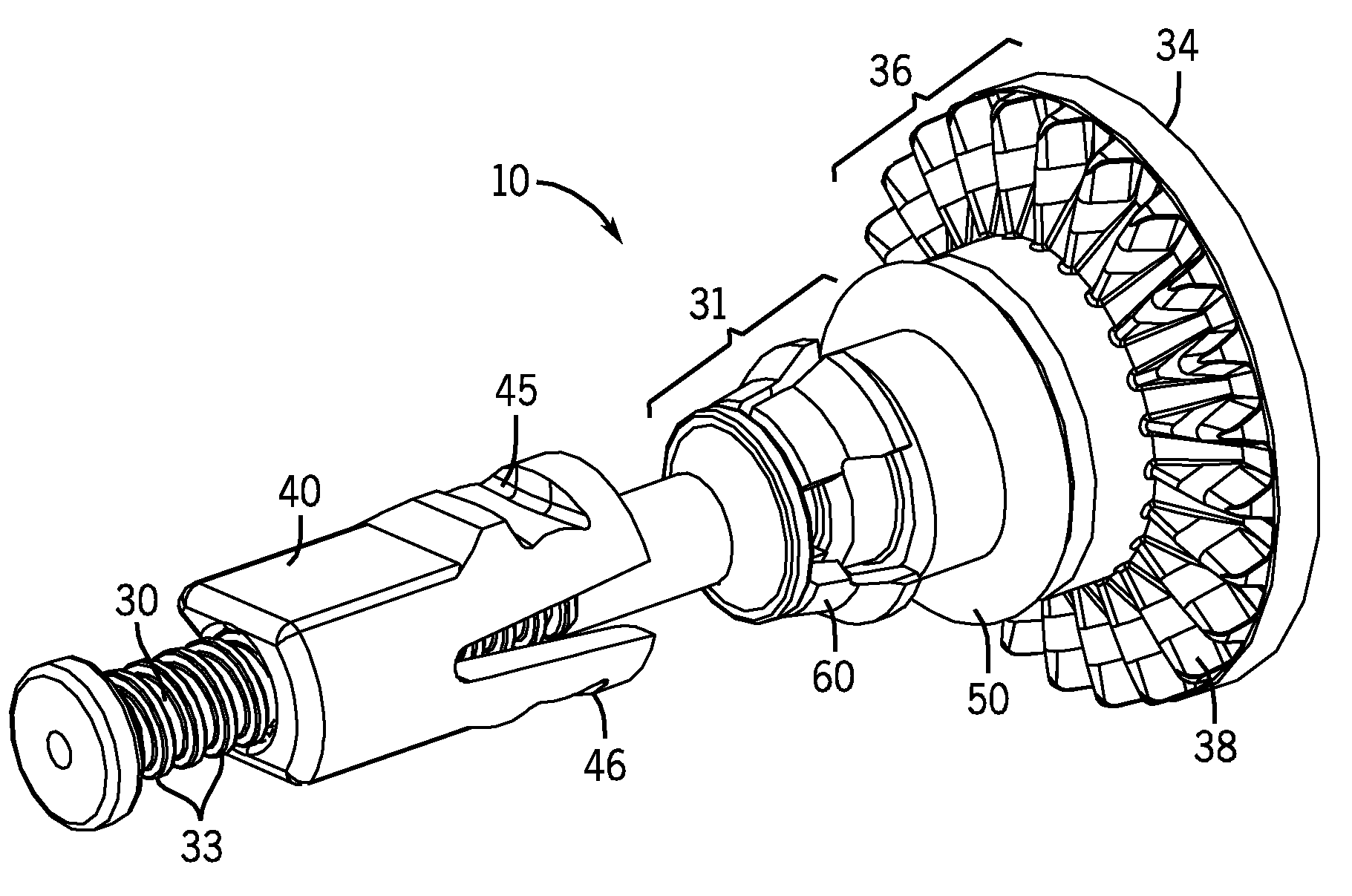
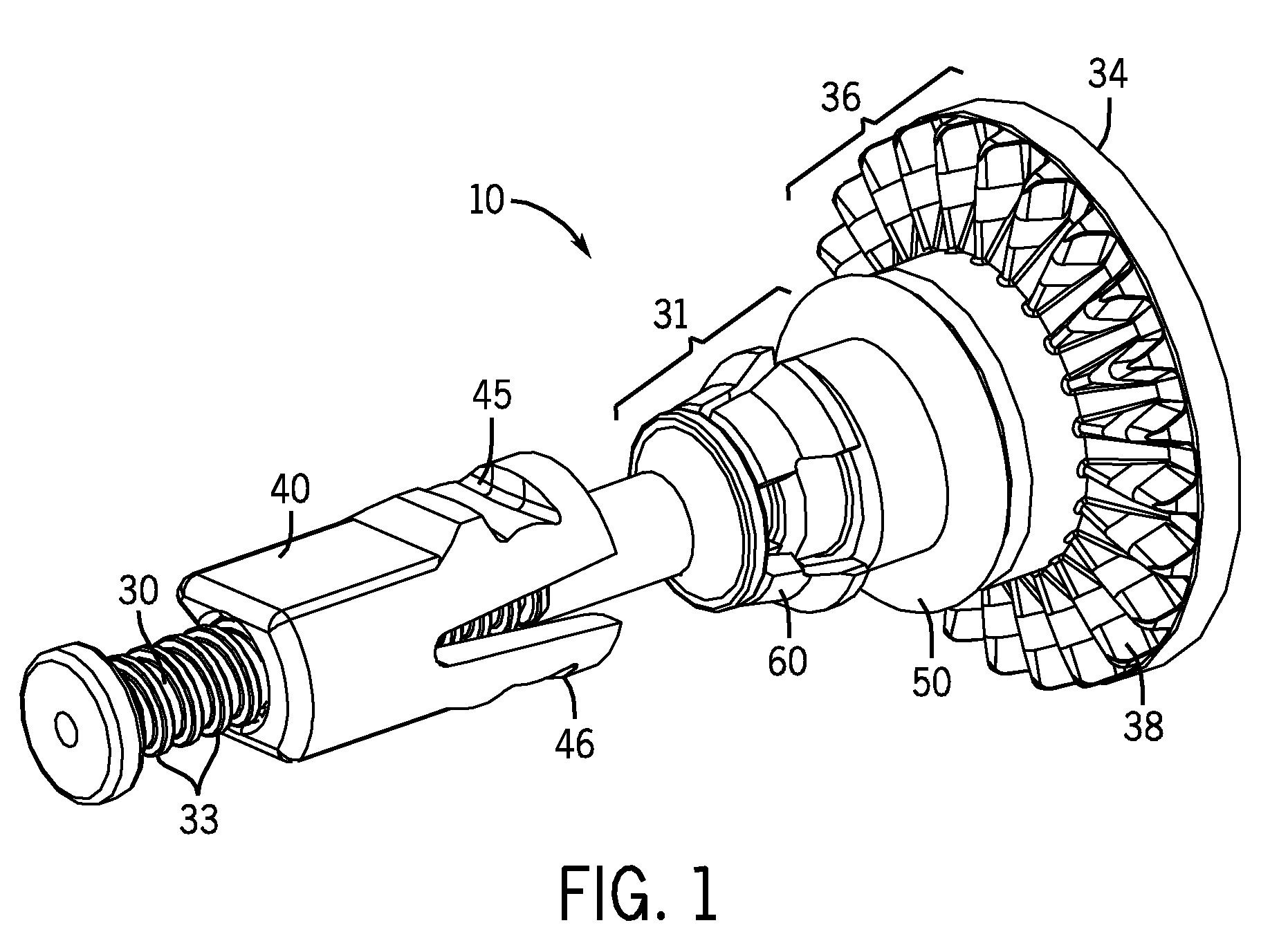
[0024]One embodiment of a gear screw adjuster assembly 10 in accordance with the present invention are shown in FIGS. 1 through 13. While the invention may be susceptible to embodiment in different forms, there is shown in the drawings, and herein will be described in detail, certain illustrative embodiments with the understanding that the present disclosure is to be considered an exemplification of the principles of the invention, and is not intended to limit the invention to those as illustrated and described herein. Additionally, features illustrated and described with respect to one embodiment could be used in connection with other embodiments.

[0025]FIG. 1 shows a gear screw adjuster 10. The adjuster 10 is used to adjust the aim of a reflector within a headlamp assembly. The headlamp assembly comprises many parts, including but not limited to, a housing 20, a movable reflector 26, a lens (not shown), and the requisite lamp and wiring (not shown). The adjuster 10 is used to adjus...


PUM


Abstract

A headlamp assembly includes a simplified adjusting mechanism for adjusting the aim of a headlamp. The mechanism includes a gear screw that is snap fit into the headlamp housing, a grommet that positioned around the gear screw and snap-fit into the headlamp reflector, and an O-ring to ensure a good seal.

Description

CROSS REFERENCE TO RELATED APPLICATIONS[0001]This application claims the benefit of provisional U.S. Application No. 61 / 013,439, filed Dec. 13, 2007, which is incorporated herein by reference under 35 U.S.C. §119(e).BACKGROUND OF THE INVENTION[0002]As the design of vehicles and automobiles has evolved, headlights have continually been reconfigured to improve the aerodynamics of the front end of the vehicle. Modern headlights are designed so that their lenses follow the contour of the vehicle to provide an aerodynamically efficient exterior surface. However, adjustment of these headlights must still be performed in order to provide an optimal beam of light and to prevent the aiming of lights beams toward oncoming vehicles. Automotive manufacturers' demand for aerodynamically efficient headlight designs has lead to modular designs requiring the headlight adjustment mechanism to be located within the engine compartment so that the adjustment can be easily performed without removing any...

Claims


Application Information

Patent Timeline
Patent Type & Authority Patents(United States)
IPC IPC(8): B60Q1/068
CPCB60Q1/0683B60Q1/068F21S41/675
Inventor BURTON, JOHN
Owner BURTON TECH
Why Eureka
Try Eureka