Disk drive mapping out data tracks to avoid thermal asperities

a technology of mapping out data tracks and data, applied in the direction of maintaining head carrier alignment, recording information storage, instruments, etc., can solve the problems of physical damage to the head, unreliable write/read performance, and disk surface agitation,

Active Publication Date: 2014-04-01
WESTERN DIGITAL TECH INC
View PDF35 Cites 72 Cited by
  • Summary
  • Abstract
  • Description
  • Claims
  • Application Information

AI Technical Summary

Problems solved by technology

An asperity may manifest on the disk surface due to a manufacturing defect of the disk, contaminates such as dust particles, friction particles due to the head sliding along a load / unload ramp, etc.
If the head strikes an asperity, it can raise the temperature of the head (thus the term thermal asperity) resulting in unreliable write / read performance as well as physically damage to the head.

Method used


Image

  • Disk drive mapping out data tracks to avoid thermal asperities
  • Disk drive mapping out data tracks to avoid thermal asperities
  • Disk drive mapping out data tracks to avoid thermal asperities

Examples


Embodiment Construction

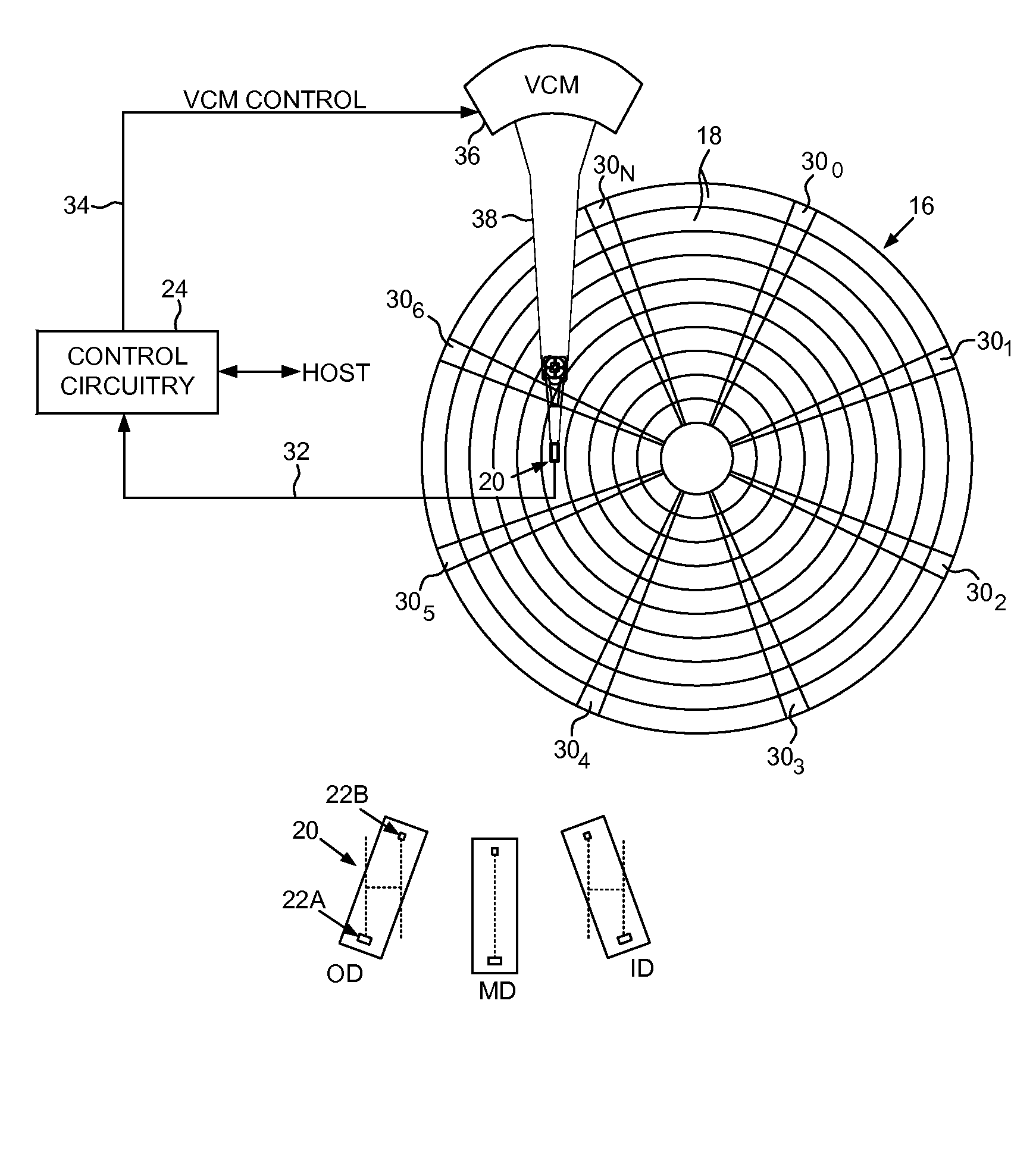
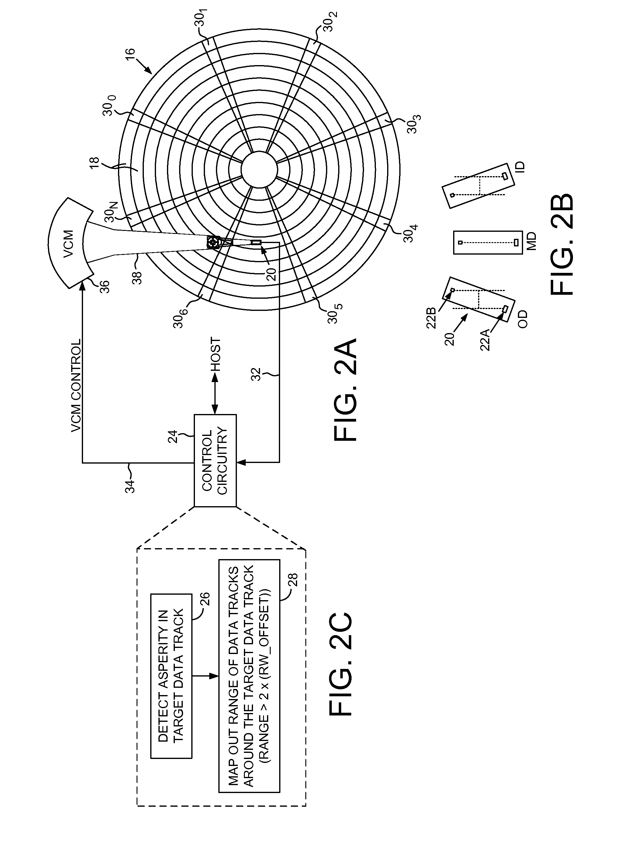
[0014]FIG. 2A shows a disk drive according to an embodiment of the present invention comprising a disk 16 having a plurality of data tracks 18, and a head 20 actuated over the disk 16, wherein the head 20 comprises a write element 22A and a read element 22B (FIG. 2B). The disk drive further comprises control circuitry 24 operable to execute the flow diagram of FIG. 2C, wherein an asperity is detected in a target data track (step 26). A range of data tracks proximate the target data track is mapped out (step 28), wherein the range of data tracks spans at least twice a radial offset between the read element and the write element at the radial location of the target data track.

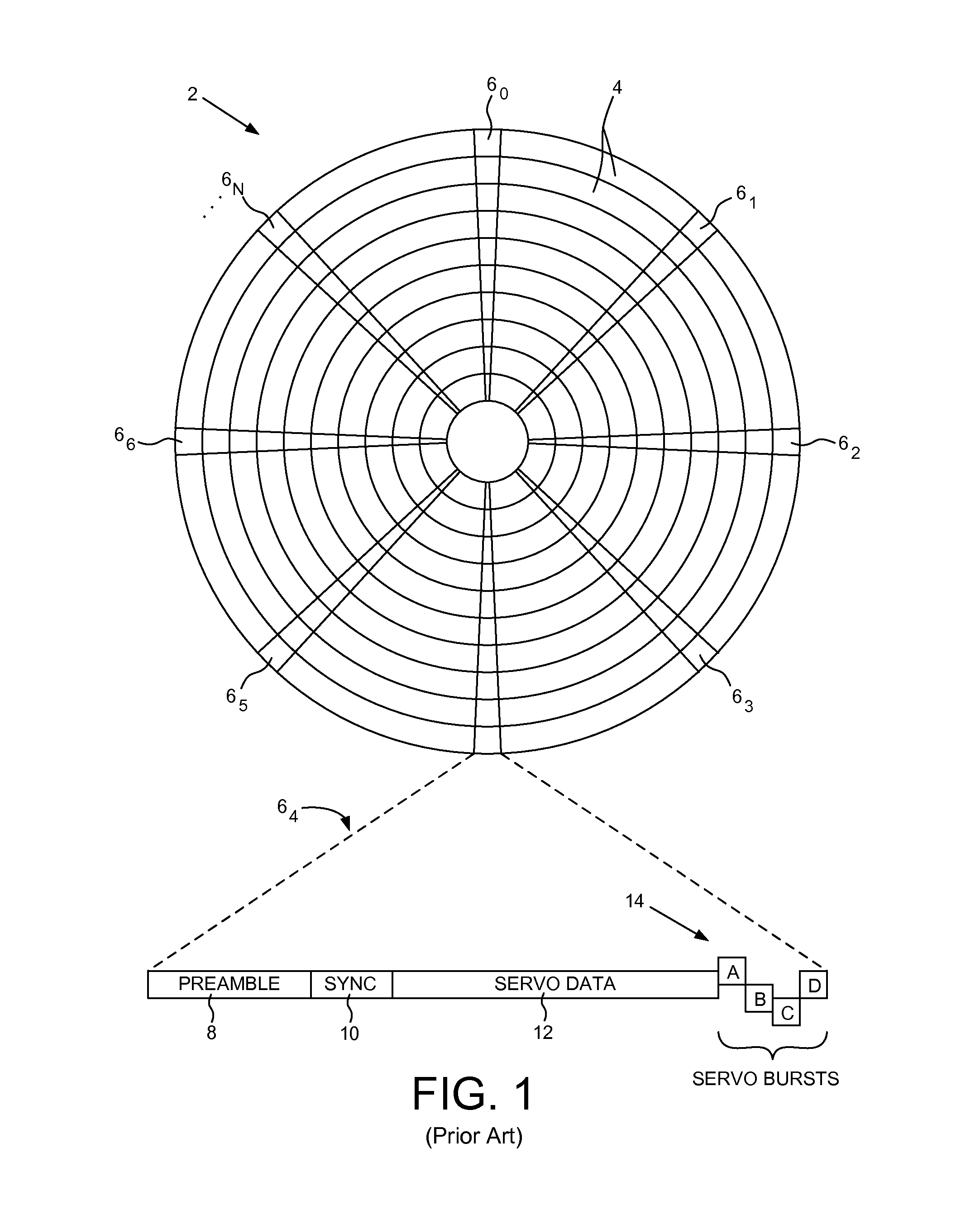
[0015]In the embodiment of FIG. 2A, the disk 16 comprises embedded servo sectors 300-30N that define the plurality of data tracks 18. The control circuitry 24 processes a read signal 32 emanating from the head 20 to demodulate the servo sectors 300-30N and generate a position error signal (PES) representing an er...


PUM

PropertyMeasurementUnit
densityaaaaaaaaaa
seek distanceaaaaaaaaaa
heightaaaaaaaaaa

Abstract

A disk drive is disclosed comprising a head actuated over a disk comprising a plurality of data tracks, wherein the head comprises a write element and a read element. An asperity in a target data track is detected, and a range of data tracks proximate the target data track is mapped out, wherein the range of data tracks spans at least twice a radial offset between the read element and the write element at the radial location of the target data track.

Description

BACKGROUNDDescription of the Related Art[0001]Disk drives comprise a disk and a head connected to a distal end of an actuator arm which is rotated about a pivot by a voice coil motor (VCM) to position the head radially over the disk. The disk comprises a plurality of radially spaced, concentric tracks for recording user data sectors and embedded servo sectors. The embedded servo sectors comprise head positioning information (e.g., a track ID) which is read by the head and processed by a servo controller to control the velocity of the actuator arm as it seeks from track to track.[0002]FIG. 1 shows a prior art format of a disk 2 comprising a plurality of concentric servo tracks 4 defined by embedded servo sectors 60-6N. Each servo sector (e.g., servo sector 64) comprises a preamble 8 for synchronizing gain control and timing recovery, a sync mark 10 for synchronizing to a data field 12 comprising the coarse head positioning information (such as a Gray coded track ID), and servo bursts...

Claims


Application Information

Patent Timeline
Patent Type & Authority Patents(United States)
IPC IPC(8): G11B21/02G11B5/596
CPCG11B2220/2516G11B2020/1298G11B2020/1241G11B5/6029
Inventor SELVARAJ, GOMEZ, SAM, VASANTHAN
Owner WESTERN DIGITAL TECH INC
Why Eureka
Try Eureka