Lighting device with controllable beam spot

A technology for lighting devices and light spots, which is applied to lighting devices, lighting device parts, lighting and heating equipment, etc., can solve the problems of difficult installation and maintenance, high cost, and increased complexity, and achieve lower product costs and simpler structure. , the effect of wide application prospects

Inactive Publication Date: 2016-03-02
SOUTHEAST UNIV
View PDF5 Cites 0 Cited by
  • Summary
  • Abstract
  • Description
  • Claims
  • Application Information

AI Technical Summary

Problems solved by technology

[0003] The existing solutions mainly realize the adjustment of the illumination beam and spot through optical and mechanical control, which brings problems of high cost; and the system volume is often relatively large, which brings certain difficulties to installation and maintenance; due to the flexibility of mechanical control The light spot form of a lamp is often fixed, so the versatility of the product is not enough, which greatly increases the cost of product design and production; at the same time, due to the mixture of optical, electrical and mechanical units, the system increases in complexity. At the same time, the stability is relatively weak

Method used


Image

  • Lighting device with controllable beam spot
  • Lighting device with controllable beam spot
  • Lighting device with controllable beam spot

Examples


Embodiment Construction

[0027] The present invention will be further clarified below in conjunction with the accompanying drawings and specific embodiments. It should be understood that these embodiments are only used to illustrate the present invention and not to limit the scope of the present invention. Modifications of equivalent forms all fall within the scope defined by the claims of the present application.

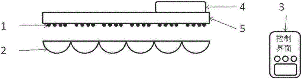
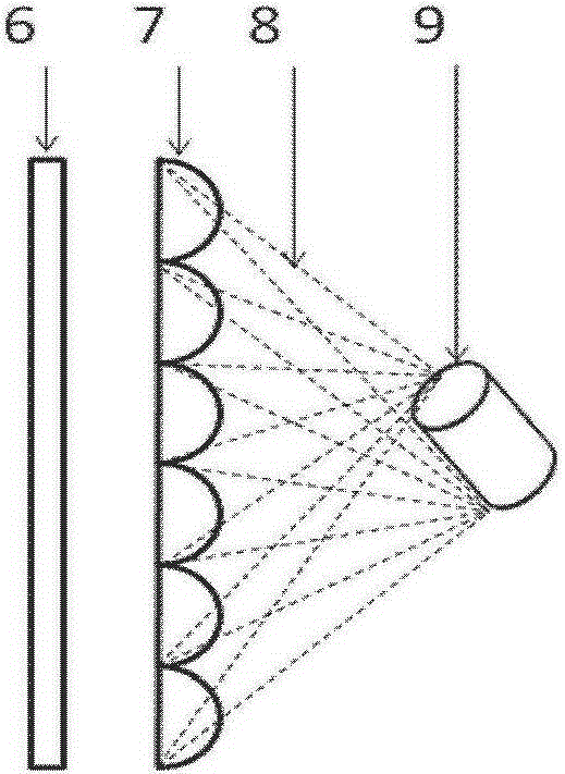
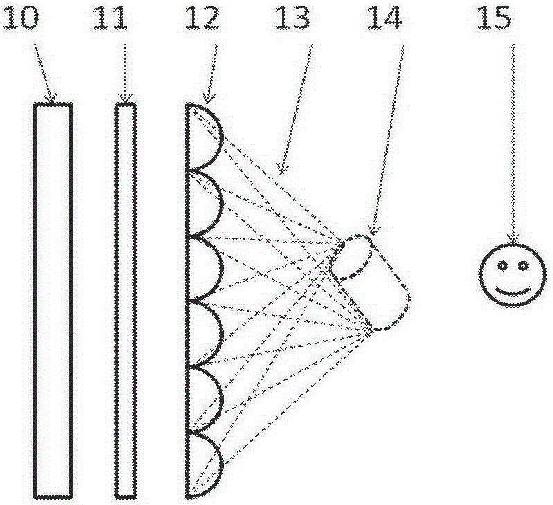
[0028] combine Figure 1 to Figure 2b The basic principle of the lighting device will be explained. like figure 1 As shown, the present invention relates to the design of a lighting device with a controllable beam spot, using an integrated lens array, based on the principle of integrated imaging, by selecting whether the array light source is lit or not, as well as the intensity and color distribution, to achieve the lighting beam and spot. control. The lighting device includes an array light source unit 1 , an integrated lens unit 2 , a target lighting effect input device 3 , a lightin...


PUM


Abstract

The invention discloses a light beam and light spot controllable illuminating device which comprises an array light source unit (1), an integrated lens unit (2), a target illuminating effect input device (3), an illuminating effect and light source drive mapping transfer device (4) and an array light source driving device (5). The integrated lens unit (2) is arranged on one side of the array light source unit (1). The target illuminating effect input device (3) is used for receiving control signals input by the outside, and the controls signals are transmitted to the illuminating effect and light source drive mapping transfer device (4). The illuminating effect and light source drive mapping transfer device (4) converts the control signals to array light source driving signals according to the relation between the control signals and the illuminating effect, and the array light source driving signals are transmitted to the array light source driving device (5). The light beam and light spot controllable illuminating device has the advantages of being simple in structure and stable in performance.

Description

technical field [0001] The present invention relates to the technical field of lighting design, and in particular, to a lighting device with controllable beam spot. Background technique [0002] In many applications, in addition to requiring lighting to provide bright functions, it is also hoped that lighting can perform functions such as atmosphere rendering, information transmission, and enhancement and highlighting, and the demand for this function occupies an increasingly important position in modern lighting design. All areas of production and life. For example, in stage lighting design, lighting is often required to provide dynamic patterns and colors; in museums, artwork lighting design requires the beam to be limited to the corresponding artwork without affecting the presentation of other artworks; in light field lighting design, it is hoped that There are flowing and changing patterns projected on the ground or curtain walls that may exist; in home lighting or open...

Claims


Application Information

Patent Timeline
Patent Type & Authority Patents(China)
IPC IPC(8): G02B27/22F21S2/00F21V5/04H05B37/02F21K9/27F21K9/60F21Y115/10
Inventor 张宇宁张晓兵雷威王保平
Owner SOUTHEAST UNIV
Why Eureka
Try Eureka