
Floor covering

a technology for floor coverings and soffits, applied in the field of floor coverings, can solve the problems of not always satisfying processing, wide and deeper grooves with a realistic appearance cannot be reproduced with the above described processing,

Active Publication Date: 2014-04-08
I4F LICENSING NV +2
View PDF8 Cites 17 Cited by
  • Summary
  • Abstract
  • Description
  • Claims
  • Application Information

AI Technical Summary

Benefits of technology

The present invention provides a floor covering that looks like tiled floors with realistic grooves. The grooves are formed by milling deeper than current methods, making them more realistic. The shape of the milled-out portion can imitate the haptic impression of the groove. No additional processing steps like printing or pressing are needed. The groove can be formed by a milling tool at the lateral edge without weakening the locking profile. The upper edges of the sidewalls of the groove are provided with bevels to avoid a sharp transition from the upper side of the panel to the groove.

Problems solved by technology

However, this processing does not always lead to satisfying results.
First of all, wider and deeper grooves with a realistic appearance cannot be reproduced with the above described processing.

Method used


Image

  • Floor covering
  • Floor covering
  • Floor covering

Examples


Embodiment Construction

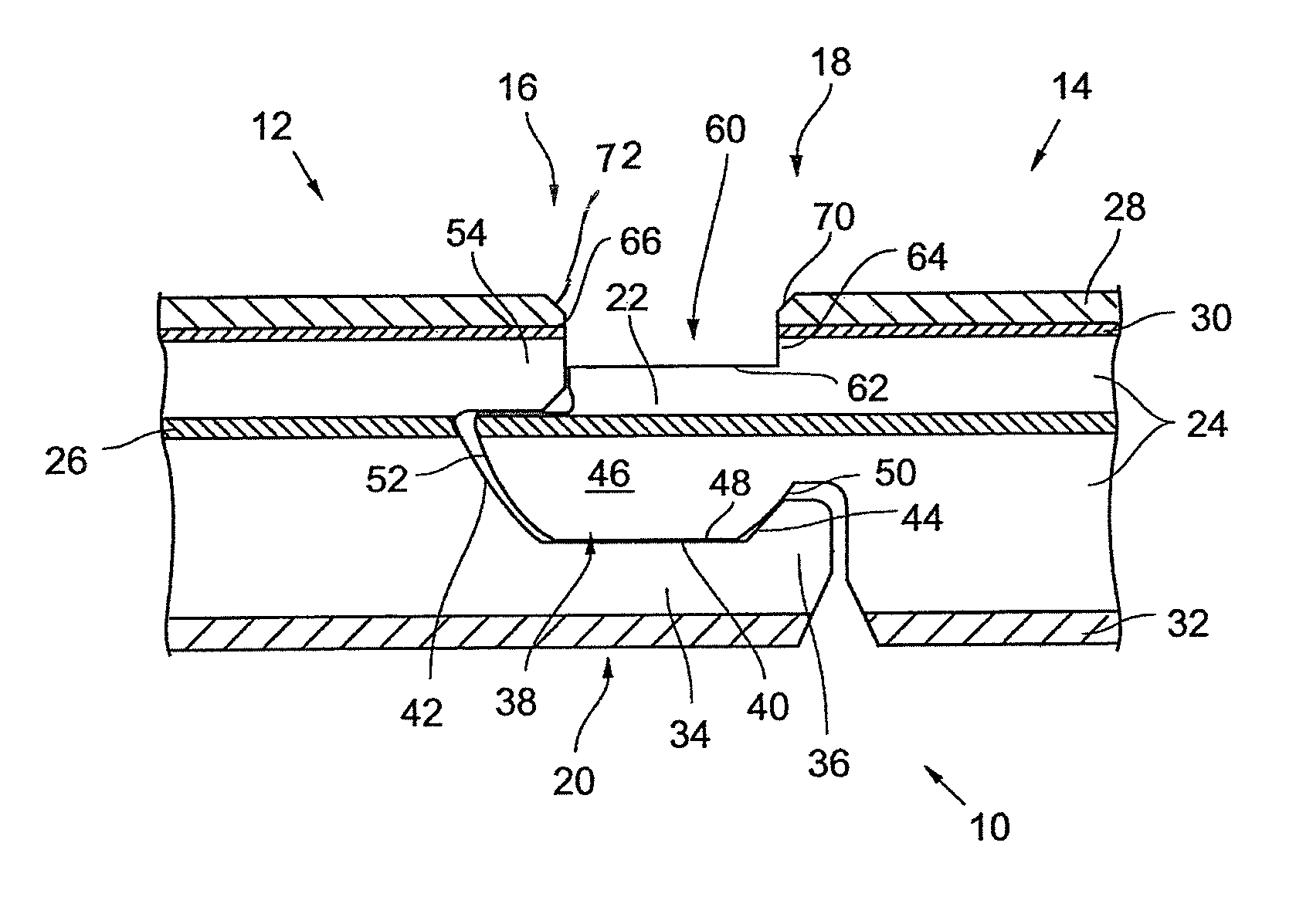
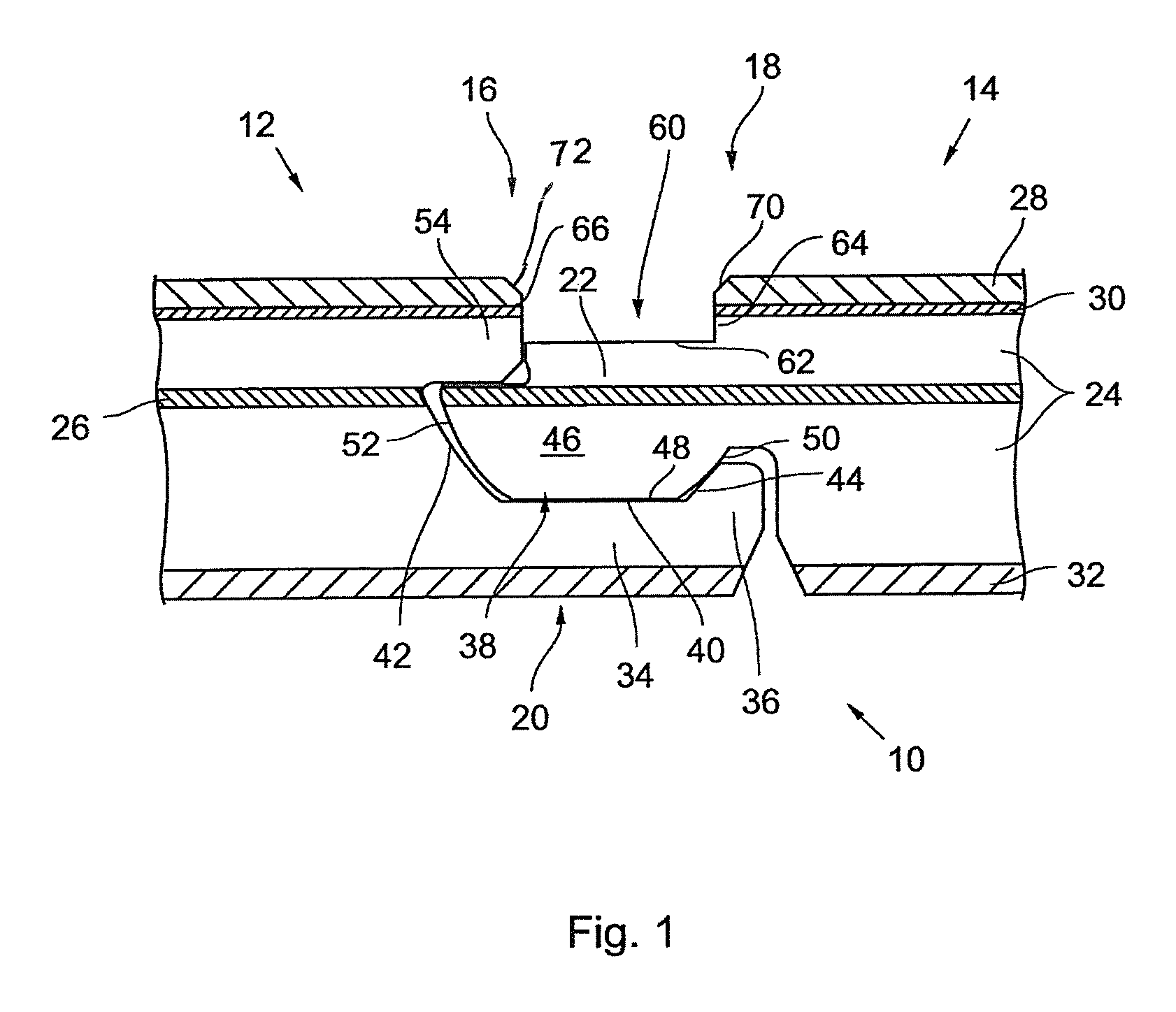
[0021]The floor covering 10 shown in FIG. 1 consists of a number of adjacent panels, from which two panels, namely a left panel 12 and a right panel 14 are shown in FIG. 1 in a connected state. The two panels 12, 14 are both provided at their connected lateral edges 16, 18 with mutually engaging form-locking profiles 20, 22, that will be further described in the following. The engagement of these locking profiles 20, 22 prevents the panels 12, 14 from drifting away from each other.

[0022]The panels 12, 14 of the floor covering 10 have the same laminate structure and comprise respectively one core 24 made of a plastic material, like polyurethane (PU) or polyvinyl-chloride (PVC). As usual, this core 24 also comprises filling materials. Because of the material characteristics of the used plastic materials, it also comprises a certain flexibility. For providing a dimensional stability of the core 24, a glass fibre mat 26 is present in the upper portion of its centre that extends horizont...


PUM

PropertyMeasurementUnit
wear resistant transparentaaaaaaaaaa
flexibleaaaaaaaaaa
widthaaaaaaaaaa

Abstract

Floor covering (10) including panels (12,14; 112) having a core (24) of a plastic material and at least one cover layer (28,30) covering the upper side of the core, the panels being provided with complementary and mutually engaging locking profiles (20,22; 120) at their connected lateral edges (16,18). For forming a groove between two connected panels (12,14; 112) at least one of these panels is provided with a milled-out portion (60,160) at the upper side of its lateral edge, with the cover layer (28,30) excavated completely over the width of the milled-out portion (60,160) so that the bottom (62,162) of the milled-out portion (60,160) is formed by the material of the core.

Description

BACKGROUND OF THE INVENTION[0001]The present invention relates to a floor covering that includes panels having a core of a plastic material and at least one cover layer covering the upper side of the core, with the panels being provided with complementary and mutually engaging locking profiles at their connected lateral edges.[0002]Floor coverings of the above kind exist in a large variety of embodiments. For example, panels with a core of wood material like MDF or HDF are very common. On top of the core there is usually a decor layer showing the appearance of wood. This decor layer is in turn covered by a transparent wear layer that is resistant against wear and may consist of a plastic material or a resin. The bottom side of the panel is formed by a back pull layer to prevent a deformation of the panel body.[0003]Moreover, floor panels comprising a core of a plastic material like PU (Polyurethane) or PVC (Polyvinylchloride) are recently available. Compared to panels of wood materi...

Claims


Application Information

Patent Timeline
Patent Type & Authority Patents(United States)
IPC IPC(8): E04B2/00
CPCE04F15/02172E04F2201/0115E04F2201/0146E04F15/105E04F15/02033E04F15/107E04F15/02038E04F15/02B44C5/04Y10T29/49826
Inventor WINDMOLLER, ULRICH
Owner I4F LICENSING NV
Learn More