Front wheel suspension for a motor vehicle

a front wheel and suspension technology, applied in the direction of resilient suspensions, vehicle components, digital data information retrieval, etc., can solve the problems of affecting the caster stiffness of the wheel suspension, the wheel recession rate, and the difficulty of maintaining the desired caster stiffness

Inactive Publication Date: 2014-04-08
FORD GLOBAL TECH LLC
View PDF38 Cites 16 Cited by
  • Summary
  • Abstract
  • Description
  • Claims
  • Application Information

AI Technical Summary

Benefits of technology

[0018]In a particular embodiment of the present invention, the asymmetric hushing 26 connecting the lower control arm 22 to the vehicle frame are structured to be relatively “soft” (i.e., to have a relatively lower stiffness responsive to forces and force components acting along the vehicle fore-aft axis or along axes parallel to the vehicle fore-aft axis, to provide a softer ride and to aid in providing a desired wheel recession rate. In addition, the bushings 26 are also structured to have a relatively greater stiffness responsive to forces and force components acting vertically with respect to the vehicle fore-aft axis (including forces acting in vertical directions (indicated by arrows C and D in FIG. 3)), to provide improved handling characteristics and to aid in providing the desired caster stiffness and brake torque / wind-up stiffness. The structures of the asymmetric bushing aids in resolving the conflicting bushing force response requirements previously described, by tailoring the bushing force response to the orientation of the threes acting on the bushing. One example of an asymmetric bushing is a known bushing having an elastomeric material positioned between inner and outer rings of the bushing, with gaps formed in portions of the elastomeric to provide a relatively lower stiffness along axes passing through the gaps, while maintaining a relatively greater stiffness along axes passing through the elastomeric. Other types of asymmetric bushings may also be used.

Problems solved by technology

However, in most suspension designs, it is necessary to position the suspension spring / damper assembly above the wheel half-shaft.
However, the spindle height affects the wheel suspension caster stiffness and the wheel recession rate.
More specifically, as the spindle height is reduced, it becomes increasingly difficult to maintain a desired caster stiffness without excessively degrading the wheel recession rate.

Method used


Image

  • Front wheel suspension for a motor vehicle
  • Front wheel suspension for a motor vehicle
  • Front wheel suspension for a motor vehicle

Examples


Embodiment Construction

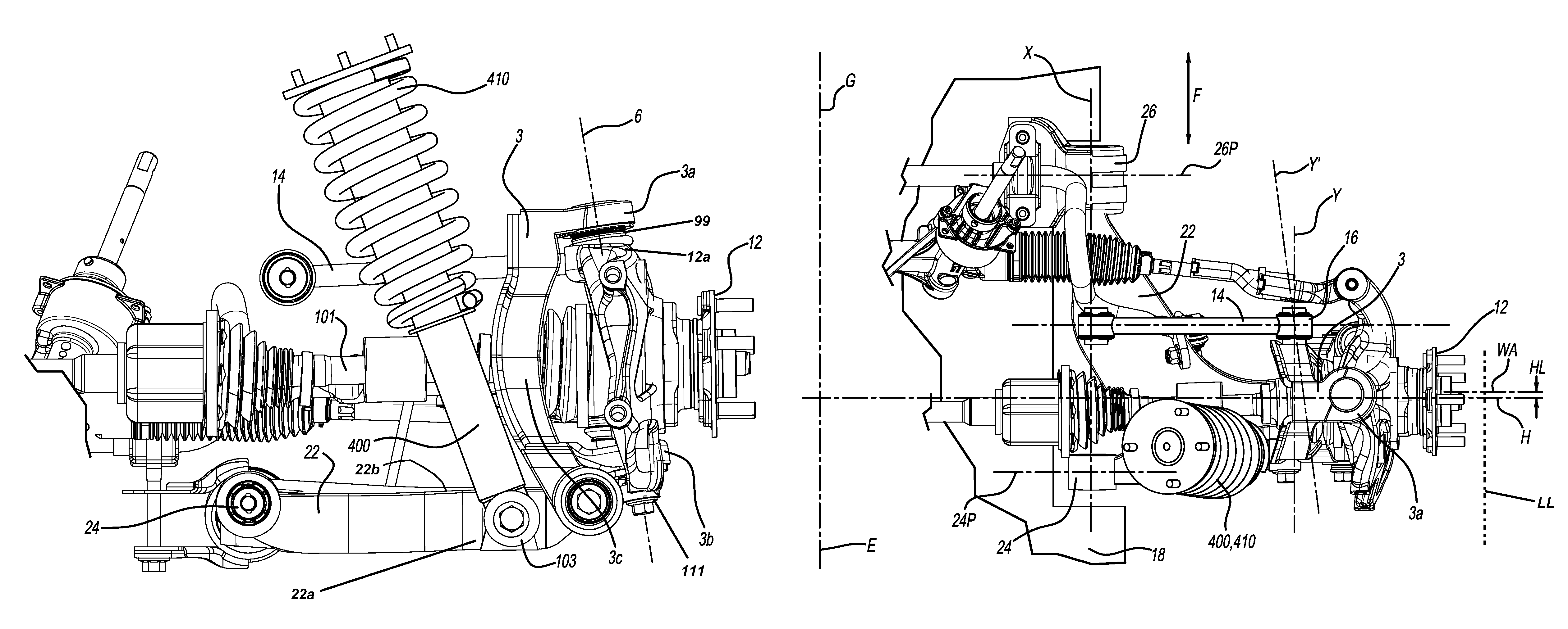
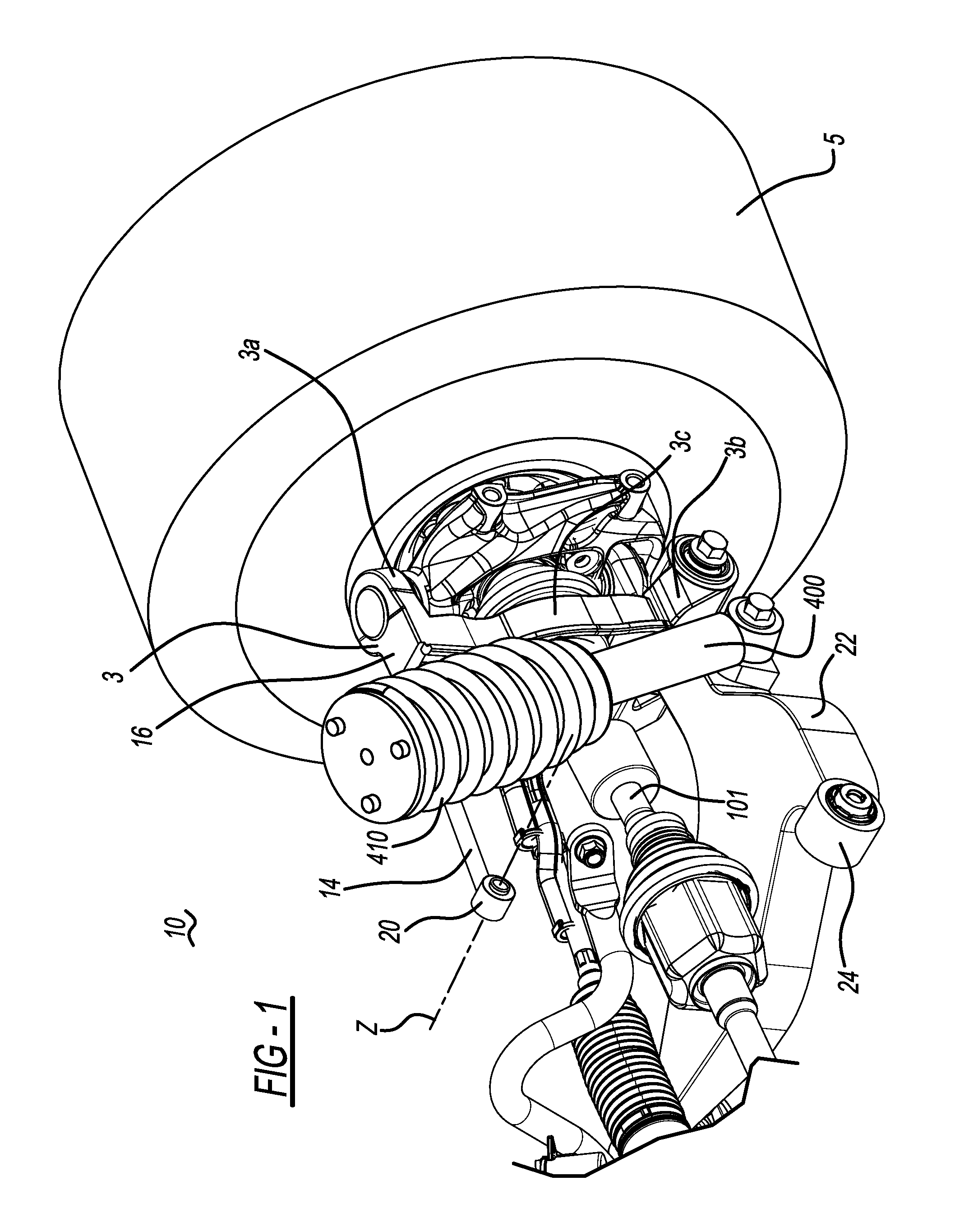
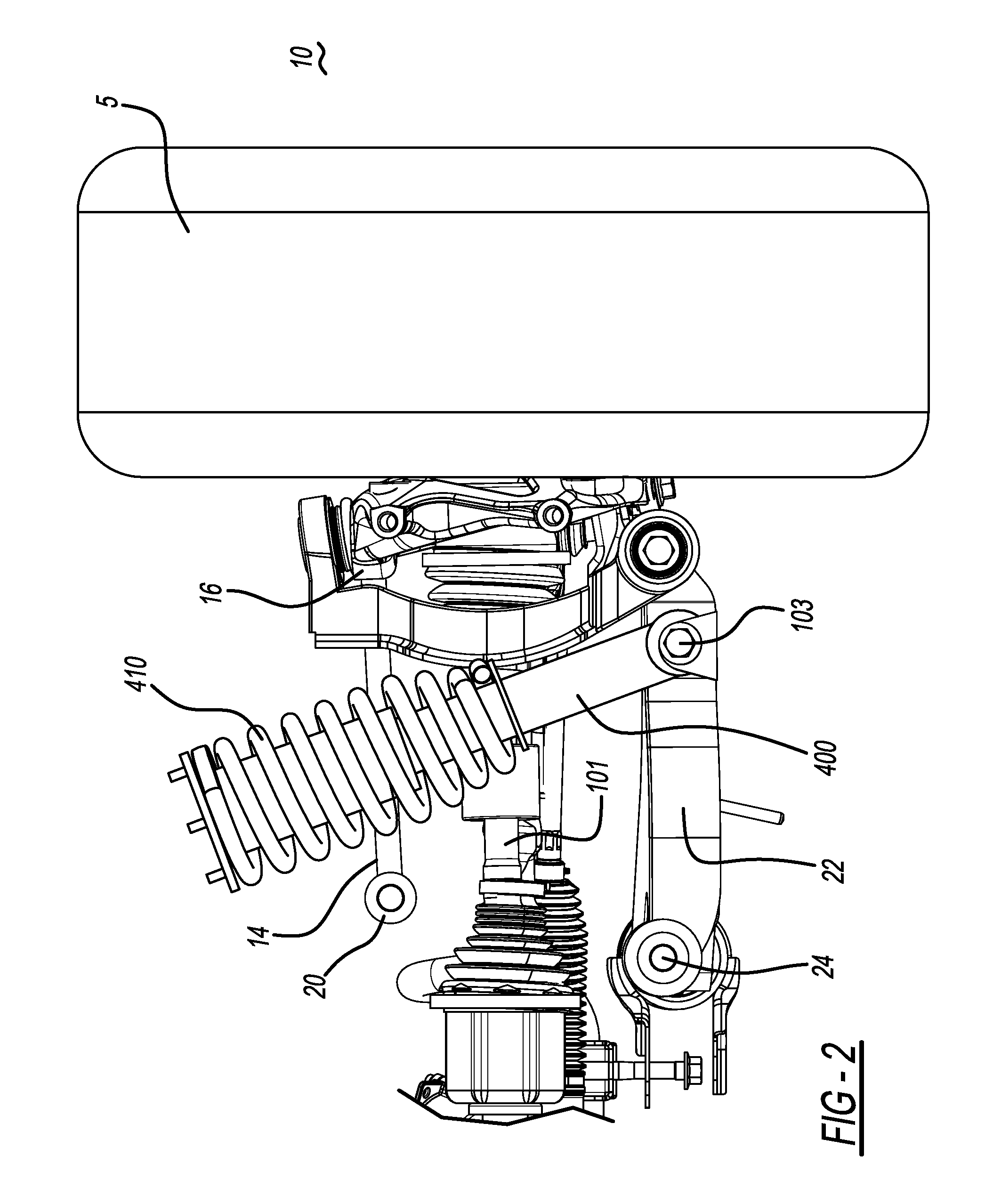
[0012]FIGS. 1-6 show a vehicle suspension assembly 10 in accordance with one embodiment of the present invention. The vehicle suspension assembly 10 may be utilized in any of a variety of vehicles. As used herein, the term “vehicle” is understood to encompass any means in or by which someone travels or something is carried or conveyed; a means of conveyance or transport. Although the embodiments of the present invention can be utilized on a variety of specific suspension designs, both front and rear, in one embodiment it is contemplated that the present invention be utilized on an automotive rear suspension.

[0013]Referring to FIGS. 1-6, the automotive suspension assembly 10 includes a vehicle suspension sub-frame 18 and a vehicle wheel bearing element 12 structured for mounting a vehicle wheel thereon and operatively coupled to the sub-frame 18 (or to another portion of the vehicle) via a first member or lower control arm 22, a carrier 3 and an upper control link 14. First member 22...


PUM


Abstract

A wheel suspension for a motor vehicle includes a carrier coupled to a portion of the vehicle, and a wheel bearing element mounted on the carrier so as to be rotatable about an axis, wherein a first portion of the carrier is rotatably coupled to the portion of the vehicle by a single link.

Description

BACKGROUND OF THE INVENTION[0001]The present invention relates to a wheel suspension system for a motor vehicle. In front-wheel drive and all-wheel drive passenger cars, it is desirable to minimize the height of the vehicle hood for styling reasons. However, in most suspension designs, it is necessary to position the suspension spring / damper assembly above the wheel half-shaft. This positioning of the suspension spring / damper assembly requires a certain amount of vertical space above the half-shaft, resulting in a relatively higher hood placement. In addition, in order to minimize hood height, it is desirable to decrease or minimize spindle height. However, the spindle height affects the wheel suspension caster stiffness and the wheel recession rate. More specifically, as the spindle height is reduced, it becomes increasingly difficult to maintain a desired caster stiffness without excessively degrading the wheel recession rate.[0002]In view of the above, it is desirable to provide ...

Claims


Application Information

Patent Timeline
Patent Type & Authority Patents(United States)
IPC IPC(8): B60G3/20
CPCG06F17/30424B60G3/06B60G2200/44B60G3/20B60G2200/144G06F16/245
Inventor BUCHWITZ, JOE LREZKALLA, JOHN SPENCERBURGESS, DAVIDBORRIES, ROBERT
Owner FORD GLOBAL TECH LLC
Why Eureka
Try Eureka