Vehicle lighting unit

a technology for vehicles and lighting, applied in vehicle interior lighting, transportation and packaging, light and heating equipment, etc., can solve the problem of less design freedom in the formation of high beam light distribution pattern, and achieve the effect of improving design freedom and high aesthetic featur

Inactive Publication Date: 2014-04-08
STANLEY ELECTRIC CO LTD
View PDF7 Cites 9 Cited by
  • Summary
  • Abstract
  • Description
  • Claims
  • Application Information

AI Technical Summary

Benefits of technology

[0012]The presently disclosed subject matter was devised in view of these and other problems and features and in view of the conventional art. According to an aspect of the presently disclosed subject matter, a vehicle lighting unit can be configured to improve design freedom (such as that for forming a high-beam light distribution pattern) and to allow an observer to visually recognize the employed projection lens even including a plurality of lens portions (including a plurality of rear-side focal points) as a single lens with high aesthetic feature.
[0014]The vehicle lighting unit with the above configuration made in accordance with principles of the presently disclosed subject matter does not include vertically arranged optical units as in the vehicle headlamp disclosed in Japanese Patent Application Laid-Open No. 2005-108554, but can include the first lens portion behind which the first optical unit is disposed and the second lens portion disposed at least on one of right side and left side of the first lens portion and behind which the second optical unit is disposed. Namely, it can include the first optical unit at the center and the second optical unit at least on one of right side and left side of the first optical unit. Therefore, the light emitted from the second optical unit can be prevented from being shielded by a shade or the like forming the first optical unit. Accordingly, the vehicle lighting unit with the above configuration is capable of improving the design freedom (such as that for forming a predetermined light distribution pattern with the light emitted from the second optical unit), meaning that, for example, the high-beam light distribution pattern can have sufficient illuminance to serve as a high-beam light distribution pattern with improved far-distance visibility.
[0015]The vehicle lighting unit with the above configuration made in accordance with principles of the presently disclosed subject matter does not include such a discontinuous lens surface with a step as in the vehicle headlamp disclosed in Japanese Patent Application Laid-Open No. 2007-109493, but can include the single continuous convex lens with a smooth continuous front surface even including the first front lens surface of the first lens portion at the center and the second front lens surface of the second lens portion on the right side and / or left side of the first lens portion. This single convex lens surface can allow an observer to visually recognize the employed projection lens even including a plurality of lens portions (including a plurality of rear-side focal points) as a single lens with high aesthetic feature.
[0023]The vehicle lighting unit with the above configuration made in accordance with principles of the presently disclosed subject matter does not include vertically arranged optical units as in the vehicle headlamp disclosed in Japanese Patent Application Laid-Open No. 2005-108554, but can include the center optical unit and the right and left optical units on both sides of the center optical unit. Therefore, the light emitted from the left and right optical units can be prevented from being shielded by a shade or the like forming the center optical unit. Accordingly, the vehicle lighting unit with the above configuration is capable of improving the design freedom (such as that for forming respective predetermined light distribution patterns with the light emitted from the left and right optical units), meaning that, for example, the predetermined light distribution patterns can have sufficient illuminance to serve as a high-beam light distribution pattern with improved far-distance visibility.
[0024]The vehicle lighting unit with the above configuration made in accordance with principles of the presently disclosed subject matter does not include such a discontinuous lens surface with a step as in the vehicle headlamp disclosed in Japanese Patent Application Laid-Open No. 2007-109493, but can include the single continuous convex lens with a smooth continuous front surface even including the center front lens surface of the center lens portion, the left front lens surface of the left lens portion, and the right front lens surface of the right lens portion. This single convex lens surface can allow an observer to visually recognize the employed projection lens even including a plurality of lens portions (including a plurality of rear-side focal points) as a single lens with high aesthetic feature.
[0032]According to the aspect of the presently disclosed subject matter, there is provided a vehicle lighting unit capable of improving design freedom (such as that for forming a high-beam light distribution pattern) and allowing an observer to visually recognize the employed projection lens even including a plurality of lens portions (including a plurality of rear-side focal points) as a single lens with high aesthetic feature.

Problems solved by technology

Therefore, the vehicle headlamp 200 can form a high-beam light distribution pattern with insufficient luminous intensity, meaning that the high-beam light distribution pattern is formed with less design freedom.

Method used


Image

  • Vehicle lighting unit
  • Vehicle lighting unit
  • Vehicle lighting unit

Examples


Embodiment Construction

[0043]A description will now be made below to vehicle lighting units of the presently disclosed subject matter with reference to the accompanying drawings in accordance with exemplary embodiments. Further, the directions of up, down (low), right, left, front, and rear (back), and the like are defined on the basis of the actual posture of a lighting unit or a headlamp installed on a vehicle body, unless otherwise specified.

[0044]A description will be given of a vehicle lighting unit 10 of a first exemplary embodiment with reference to the accompanying drawings.

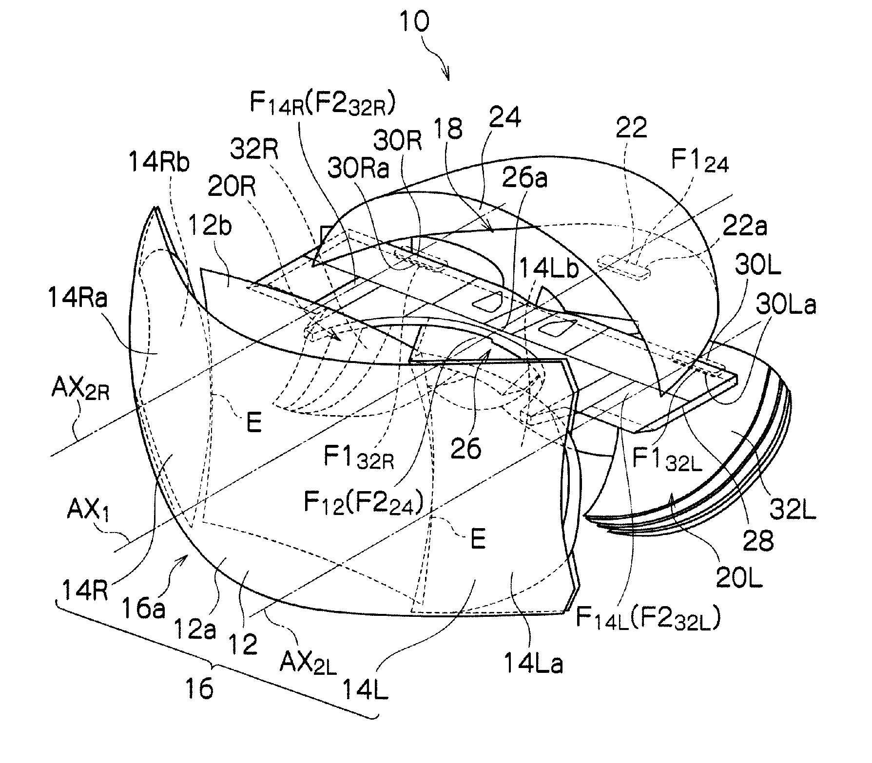
[0045]FIG. 3 is a perspective view showing the vehicle lighting unit 10 according to the first exemplary embodiment made in accordance with the principles of the presently disclosed subject matter, and FIGS. 4, 5, and 6 are a front view, a side view and a top plan view of the vehicle lighting unit 10 of FIG. 3, respectively.

[0046]As shown in FIGS. 3 to 6, the vehicle lighting unit 10 of the present exemplary embodiment can be a...


PUM


Abstract

A vehicle lighting unit is capable of improving the design freedom (such as that for forming a high-beam light distribution pattern) and to allow an observer to visually recognize the employed projection lens even when including a plurality of lens portions (including a plurality of rear-side focal points) as a single lens with high aesthetic feature.

Description

[0001]This application claims the priority benefit under 35 U.S.C. §119 of Japanese Patent Application No. 2012-013197 filed on Jan. 25, 2012, which is hereby incorporated in its entirety by reference.TECHNICAL FIELD[0002]The presently disclosed subject matter relates to vehicle lighting units, and in particular, to a vehicle lighting unit for use in a vehicle headlamp, or the like.BACKGROUND ART[0003]Conventional vehicle headlamps may include upper and lower optical units each utilizing a semiconductor light emitting device, such as those disclosed in Japanese Patent Application Laid-Open No. 2005-108554 (JP4044024B or U.S. Patent Publication No. 2005 / 0068787A1 corresponding thereto) and Japanese Patent Application Laid-Open No. 2007-109493 (JP4615417B or U.S. Patent Publication No. 2007 / 0086202A1 corresponding thereto).[0004]FIG. 1 is a vertical cross-sectional view of a conventional vehicle headlamp 200 described in Japanese Patent Application Laid-Open No. 2005-108554.[0005]As s...

Claims


Application Information

Patent Timeline
Patent Type & Authority Patents(United States)
IPC IPC(8): B60Q1/00
CPCF21S41/147F21S41/26F21S41/40F21S41/663F21S41/148F21V13/12
Inventor SEKIGUCHI, TATSUYA
Owner STANLEY ELECTRIC CO LTD
Why Eureka
Try Eureka