Flat panel display mount

a technology for mounting systems and displays, applied in the direction of machine supports, instruments, electrical apparatus casings/cabinets/drawers, etc., can solve the problems of lowering the aesthetic appeal of a costly device bought chiefly for its aesthetics, affecting the aesthetics of the device, so as to achieve easy adjustment and rotation of the display

Active Publication Date: 2014-04-08
LEGRAND AV INC
View PDF25 Cites 49 Cited by
  • Summary
  • Abstract
  • Description
  • Claims
  • Application Information

AI Technical Summary

Benefits of technology

[0008]A mounting system for a flat panel display includes a back assembly, a pair of arm assemblies, and a mounting assembly. Back assembly can include a slide plate connected to arm assemblies which allows arm assemblies and mount assembly to be horizontally shifted without the need to remove the mount from the wall and reattach it. Arm assemblies can include substantially hollow arms having removable covers for storing wires connected to display therein. Mounting assembly can include a tilt head that provides a path of rotation about a substantially horizontal axis that extends proximate the center of gravity of the mount and a flat panel display mounted thereon, allowing for easy adjustment and rotation of display. Mounting assembly can also include a pair of brace arms each comprised of two members configured to allow mount assembly to be expanded to mount various sized displays without extending beyond the width of the display.

Problems solved by technology

The display image is often too dark or not visible at all if viewed from a significant angle.
However, when mounting brackets of a mounting device that is capable of mounting a wider display are brought closer together for mounting a narrower display, the brace arms upon which the mounting brackets slide can stick out beyond the width of the display, lowering the aesthetic appeal of a costly device bought chiefly for its aesthetics.
These wires tend to hang out in the open, which also tends to distract from the aesthetics of the flat panel display.
The wires also have a tendency to become tangled, which makes it more difficult to remove or adjust the flat panel display and / or other devices.

Method used


Image

  • Flat panel display mount
  • Flat panel display mount
  • Flat panel display mount

Examples


Embodiment Construction

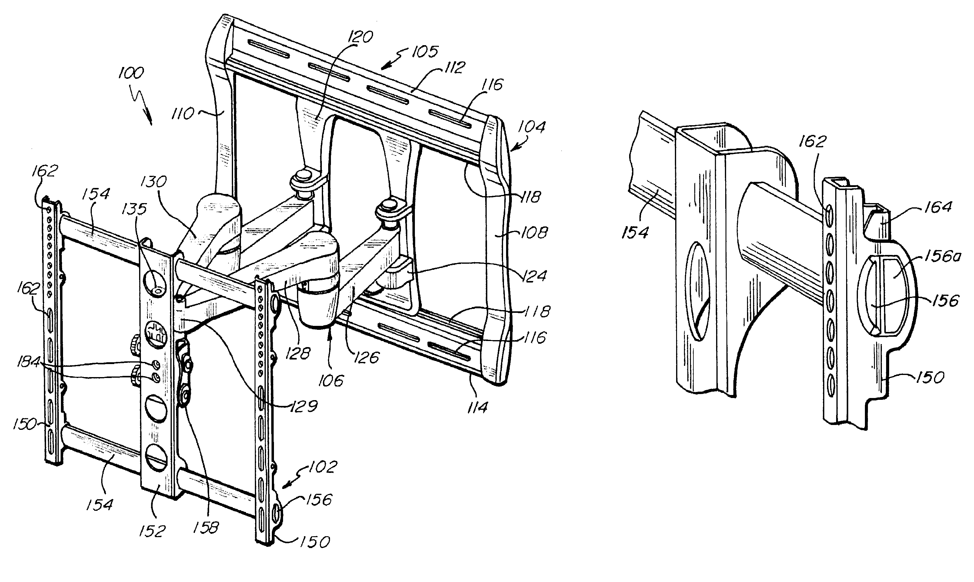
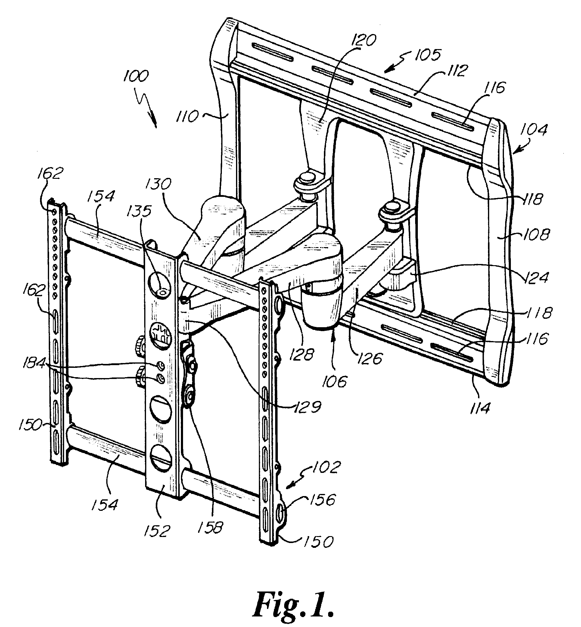
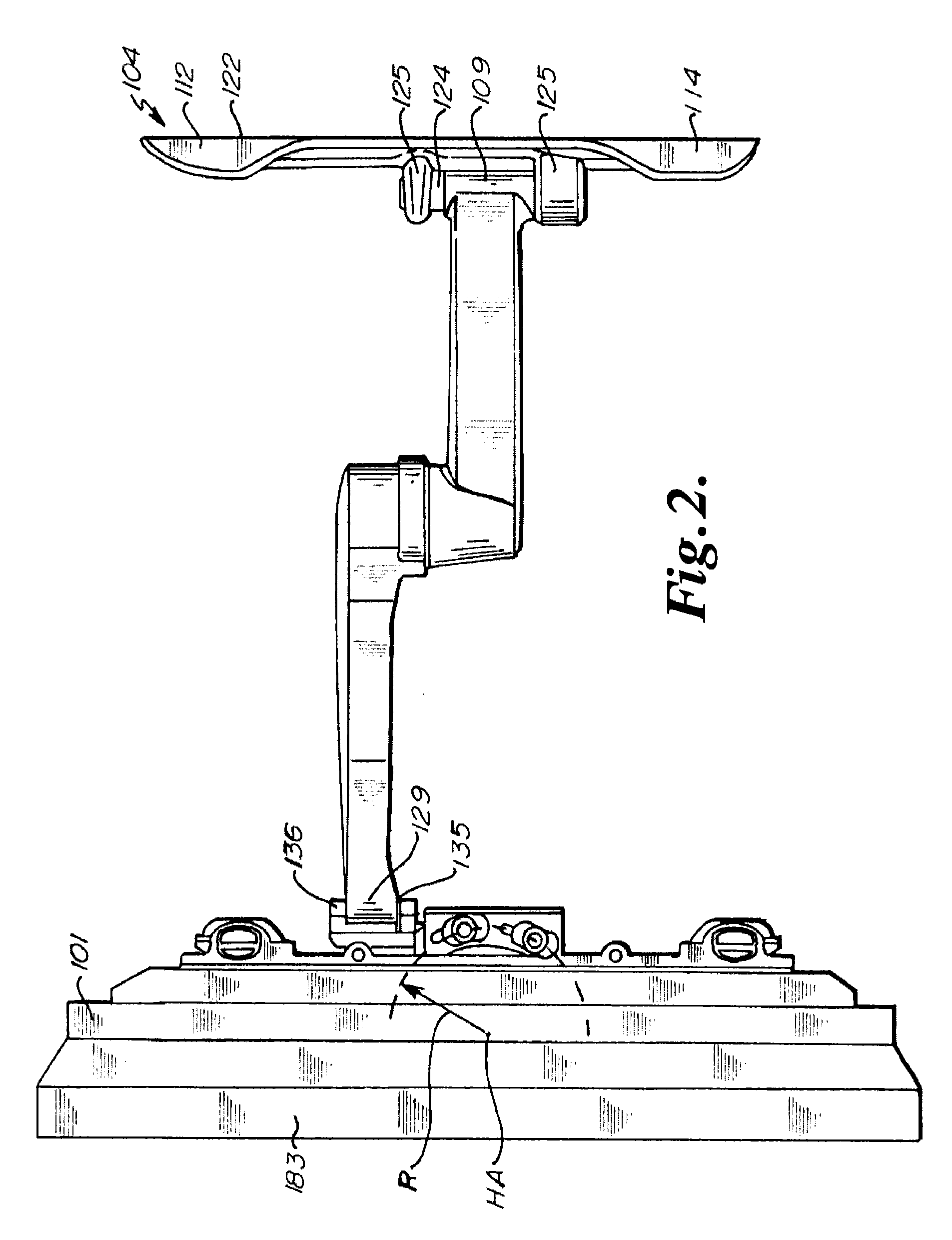
[0044]FIGS. 1-17 show a first embodiment of a display mount 100 of the present invention. Display mount 100 is configured to mount an interface such as a flat panel display, such as a computer monitor or television. Referring to FIGS. 1-3, display mount 100 generally includes a mounting assembly 102 and a back assembly 104 connected by a pair of arm assemblies 106.

[0045]Back assembly 104 can include a generally rectangular support 105. Support 105 can include a pair of side rails 108, 110, a top rail 112 and a bottom rail 114. Side rails 108, 110, top rail 112, and bottom rail 114 define a back surface 122 that can be mounted flush with a wall or other support surface.

[0046]Top rail 112 and bottom rail 114 can include a plurality of elongated mounting slots 116. Mounting slots 116 are configured to allow back assembly 104 to be mounted to a wall or other support surface. The elongated nature of mounting slots 116 provides for flexibility in positioning display mount 100 relative to ...


PUM


Abstract

A mounting system for a flat panel display includes a back assembly, a pair of arm assemblies, and a mounting assembly. Back assembly can include a slide plate connected to arm assemblies allowing arm assemblies and mount assembly to be horizontally shifted without the need to remove the mount from the wall and reattach it. Arm assemblies can include substantially hollow arms having removable covers for storing wires connected to display therein. Mounting assembly can include a tilt head that provides a path of rotation about a substantially horizontal axis that extends proximate the center of gravity of the mount and a flat panel display mounted thereon, allowing for easy adjustment and rotation of display, Mounting assembly can also include a pair of brace arms each comprised of two members configured to allow mount assembly to be expanded to mount various sized displays without extending beyond the width of the display.

Description

RELATED APPLICATIONS[0001]The present Application claims the benefit of U.S. Provisional Application No. 61 / 019,112, filed Jan. 4, 2008, which is hereby fully incorporated herein by reference.FIELD OF THE INVENTION[0002]The present invention relates to flat panel display mounting systems, and more particularly to selectively adjustable flat panel display mounting systems.BACKGROUND OF THE INVENTION[0003]Flat panel displays have become an increasingly popular substitute for projection devices and CRT's. The flat panel display is typically mounted on a structure, such as a wall. Flat panel displays, especially LCD displays, are typically most clearly viewable from a position directly in front of the display. The display image is often too dark or not visible at all if viewed from a significant angle.[0004]It is thus preferable that the angle of a flat panel display can be adjusted for optimum viewing. Various prior art positioning devices have been used, such as friction based hinges,...

Claims


Application Information

Patent Timeline
Patent Type & Authority Patents(United States)
IPC IPC(8): G06F1/16H05K7/14
CPCY10S248/924F16M2200/065F16M11/10F16M11/2092F16M13/02F16M11/38F16M11/2085Y10S248/921F16M11/04F16M11/2014F16M11/08G06F1/1637Y10S248/923
Inventor RUSSELL, SCOTTSTANEK, NICKPFISTER, JOEL W.
Owner LEGRAND AV INC
Why Eureka
Try Eureka