Roof reflector

a technology of reflector and roof, which is applied in the direction of roof covering insulation, building components, plant protection, etc., can solve the problems of air conditioning units not operating at their optimal, no good thermal insulation characteristics of these materials, and poor thermal insulation of materials

Inactive Publication Date: 2014-04-15
KING FAHD UNIVERSITY OF PETROLEUM AND MINERALS
View PDF38 Cites 13 Cited by
  • Summary
  • Abstract
  • Description
  • Claims
  • Application Information

AI Technical Summary

Problems solved by technology

Such roofing materials generally include tar and / or other petroleum based products, which materials are very poor thermal insulators.
While other materials are sometimes used for roofing, e.g., composite glass fiber sheets, ceramic tiles, etc., none of these materials possess good thermal insulating characteristics.
Ever increasing energy costs often result in such air conditioning units not being operated at their optimum, with temperatures within the structure being somewhat warmer than is comfortable for the occupants.
The opposite problem often occurs in colder climates, so that the heat escapes through the poorly insulated roofing, resulting in cooler than comfortable temperatures for occupants of the structure.

Method used


Image

  • Roof reflector
  • Roof reflector
  • Roof reflector

Examples


embodiment 200

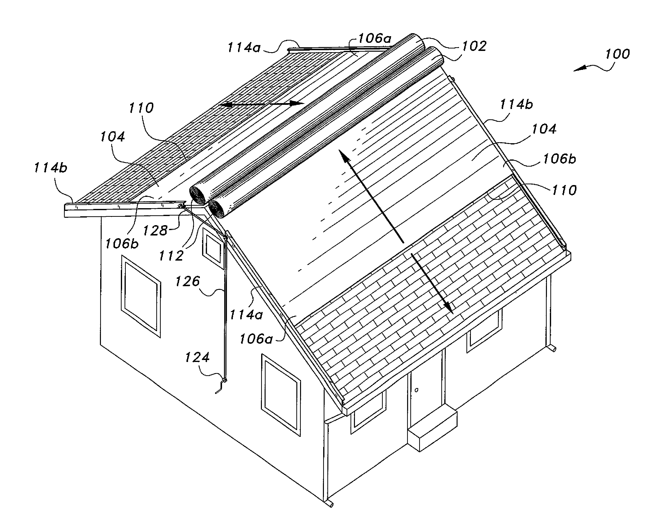
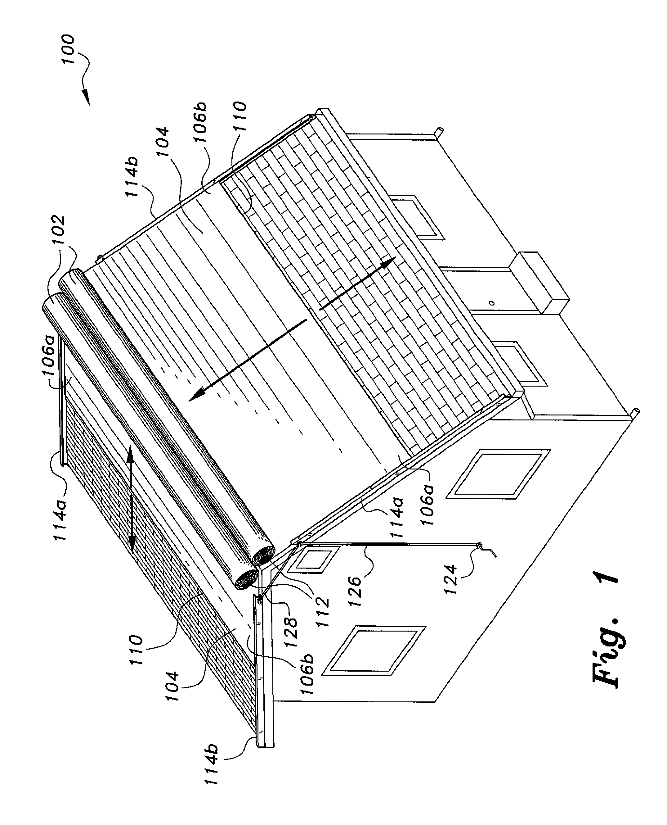
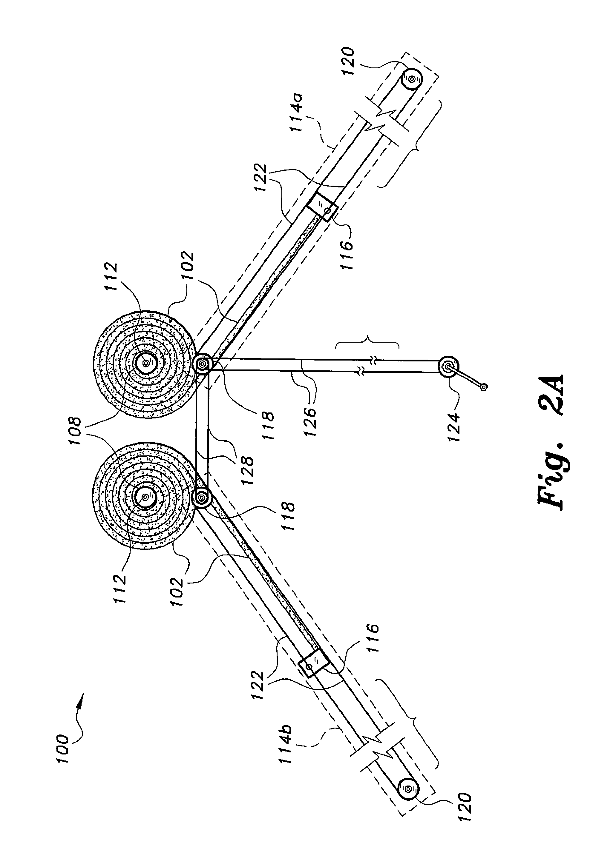
[0033]The cable 320 and pulleys 316, 318 are actuated by a remotely located hand crank 324 that actuates a drive cable 326, these components being equivalent to the crank 124 and drive cable 126 of the blanket-type roof reflector 100 of FIGS. 1 and 2A. Alternatively, the electric motor 226 and electronic control switch or panel unit 224 of the embodiment 200 of FIG. 2B may be substituted for the crank 324 and drive cable 326 in the roof reflector 300 of FIG. 3, if desired.

[0034]The roof reflector 400 of FIG. 4 also includes a plurality of rigid panels, but the panels of the roof reflector 400 telescope into one another for retraction and storage, rather than folding. FIG. 4 shows three rigid telescoping panels, comprising a fixed upper panel 402, a single intermediate panel 404, and a lower panel 406. As in the roof reflector 300 of FIG. 3, as few as a single movable telescoping lower panel may be provided, or multiple intermediate panels may be provided. Each of the panels 402, 404...

fifth embodiment

[0037]FIG. 5 of the drawings provides an illustration of the roof reflector 500, comprising a plurality of laterally disposed, parallel, and adjustable rigid panels or slats. As few as two such panels or slats (comprising an upper panel and a lower panel) may be provided, but preferably a plurality of intermediate panels or slats, e.g., 502b through 502h, are provided between the uppermost panel or slat 502a and the lowermost panel or slat 502i. In the roof reflector 500 of FIG. 5, two substantially identical multiple panel or slat systems are provided, one to each side of the ridge or crest of the roof. It will be seen that this basic concept of applying like systems to both slopes or sides of a gabled roof will also apply to the roof reflectors 300 and 400 of FIGS. 3 and 4, where the second system is not shown for clarity in the drawing Figs.

[0038]Each of the panels or slats 502a through 502i has mutually opposed first and second ends 504a through 504i and 506a through 506i. An up...

embodiment 500

[0041]The pulley 508 and its cables 516a through 516c are actuated by a remotely located hand crank 524 that actuates a drive cable 526, these components being equivalent to the crank 124 and drive cable 126 of the blanket-type roof reflector 100 of FIGS. 1 and 2A and the corresponding crank 324 and cable 326 of the roof reflector 300 of FIG. 3 and the crank 424 and cable 426 of the roof reflector of FIG. 4. Alternatively, the electric motor 226 and electronic control switch or panel unit 224 of the roof reflector 200 of FIG. 2B may be substituted for the crank 524 and drive cable 526 in the multiple panel or slat roof reflector embodiment 500 of FIG. 5.

[0042]FIG. 6 provides an end elevation view in section of an alternative embodiment of the wheeled guides and eaves tracks used to draw the thermal blanket up and down over the surface of the roof. The two eaves E1 and E2 are shown in section, in mirror image to one another. Mutually opposed first and second upper angles, respectivel...


PUM


Abstract

The roof reflector provides selectively deployable and retractable devices for installation over the roof of a building structure to reduce the amount of solar energy transmitted to the roof proper. The roof reflector may include a thick roll of insulating material that may be unrolled to cover the roof or rolled up for storage. Alternatively, the roof reflector may have a plurality of rigid panels hinged together to extend over the roof or to fold over one another for storage. Yet another alternative is a plurality of rigid panels that telescope into one another for storage. Still another alternative includes a plurality of laterally disposed slats that may be opened and closed in the manner of Venetian blinds. The roof reflector is remotely operated, either mechanically by a hand crank and cable mechanism, or electronically by a remote signal operating an electric motor.

Description

CROSS REFERENCE TO RELATED PATENT APPLICATION[0001]This application is a continuation-in-part of U.S. patent application Ser. No. 13 / 472,309 filed on May 15, 2012.BACKGROUND OF THE INVENTION[0002]1. Field of the Invention[0003]The present invention relates to protective covers for structures, and particularly to various embodiments of a roof reflector that is selectively deployable, serving to reduce solar heating of the underlying structure when deployed.[0004]2. Description of the Related Art[0005]The conventional roof of a building structure is constructed of materials that are capable of resisting the deleterious effects of sunlight (including ultraviolet energy) and weather for a prolonged period, generally at least one or more decades. Accordingly, the materials used for such roofing are selected for their durability, rather than their energy reflecting properties. Such roofing materials generally include tar and / or other petroleum based products, which materials are very poor...

Claims


Application Information

Patent Timeline
Patent Type & Authority Patents(United States)
IPC IPC(8): B62D63/04E06B9/17E04B7/00E06B9/56A01G13/02E04H9/00E04H14/00
CPCE04D13/1606E04D13/16Y02P60/12
Inventor DONDURUR, MEHMETSAHIN, AHMET Z.
Owner KING FAHD UNIVERSITY OF PETROLEUM AND MINERALS
Why Eureka
Try Eureka