
Method and apparatus for suppression of oscillations in a rolling installation

a technology of oscillation suppression and rolling installation, which is applied in the direction of rolling mill control devices, metal rolling arrangements, manufacturing tools, etc., can solve the problems of affecting so as to improve the quality of rolled materials and/or the productivity of rolling installations. , the effect of suppressing oscillation

Active Publication Date: 2014-04-15
PRIMETALS TECH AUSTRIA GMBH
View PDF18 Cites 3 Cited by
  • Summary
  • Abstract
  • Description
  • Claims
  • Application Information

AI Technical Summary

Benefits of technology

The patent text describes a method and apparatus for reducing vibrations in a rolling installation, especially the 3rd-octave oscillations, to improve the quality of the material and increase productivity. The technical effect is to suppress the vibrations, resulting in better quality materials and higher productivity.

Problems solved by technology

In the case of rolling installations, in particular cold rolling lines, it is known for undesirable oscillations to occur in certain operating states, for example strip tension, strip tension difference, coefficients of friction, thickness decrease, material strength and strip velocity, and these oscillations can lead to considerable damage to the installation, as well as to defects in the rolled material.
3rd-octave oscillations typically occur in a frequency range from about 80 to 170 Hz, and are characterized by a high energy content and unstable oscillating states, as a result of which considerable mechanical damage can also occur to the rolling stand of a rolling installation.
Since, however, these oscillations also lead to movements of the roller set and therefore to discrepancies from the nominal rolling gap, this leads to defects in the rolled material, which may be in the form of surface defects, geometric defects or else combinations thereof.
Typically, when oscillations such as these occur, the personnel operating the rolling installation will immediately reduce the rolling speed, which involves a reduction in throughput (that is to say reduced productivity), and leads to the oscillations decaying.

Method used


Image

  • Method and apparatus for suppression of oscillations in a rolling installation
  • Method and apparatus for suppression of oscillations in a rolling installation
  • Method and apparatus for suppression of oscillations in a rolling installation

Examples


Embodiment Construction

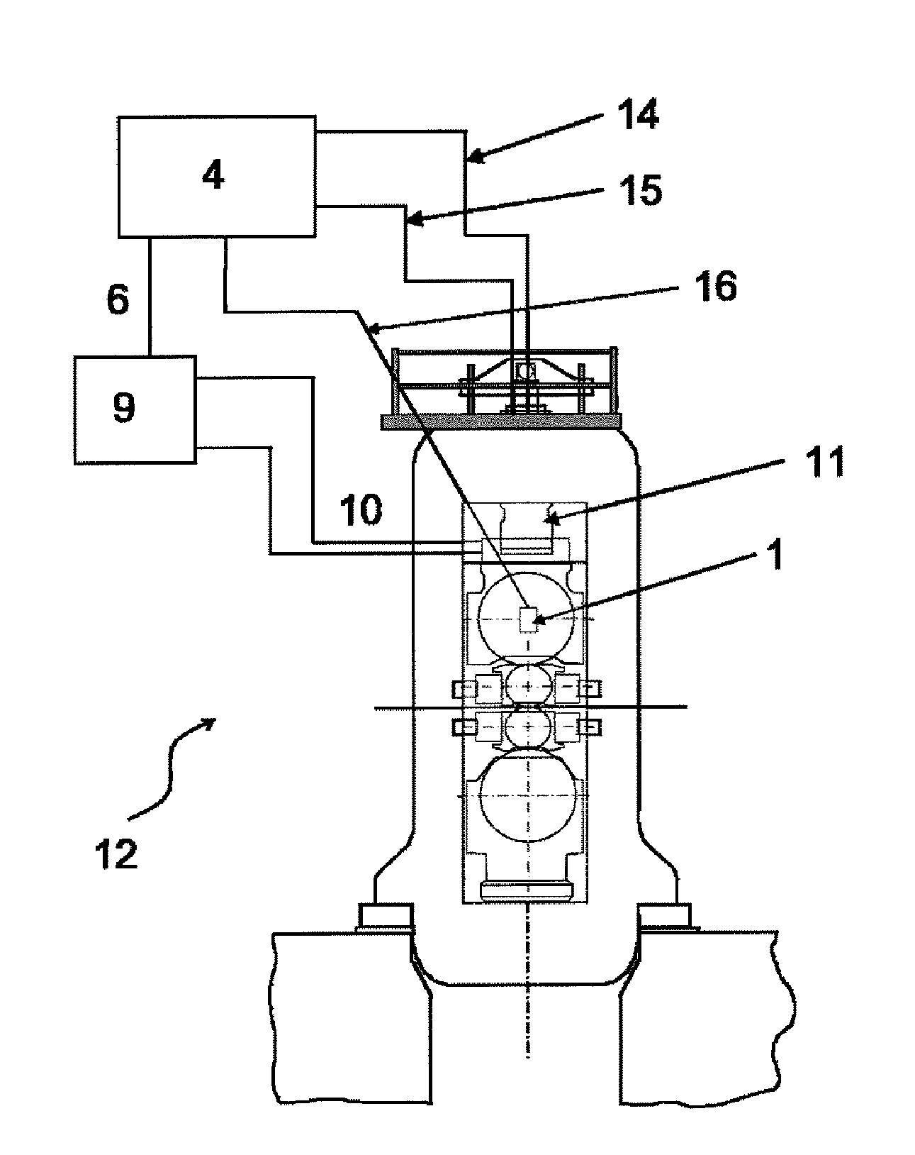
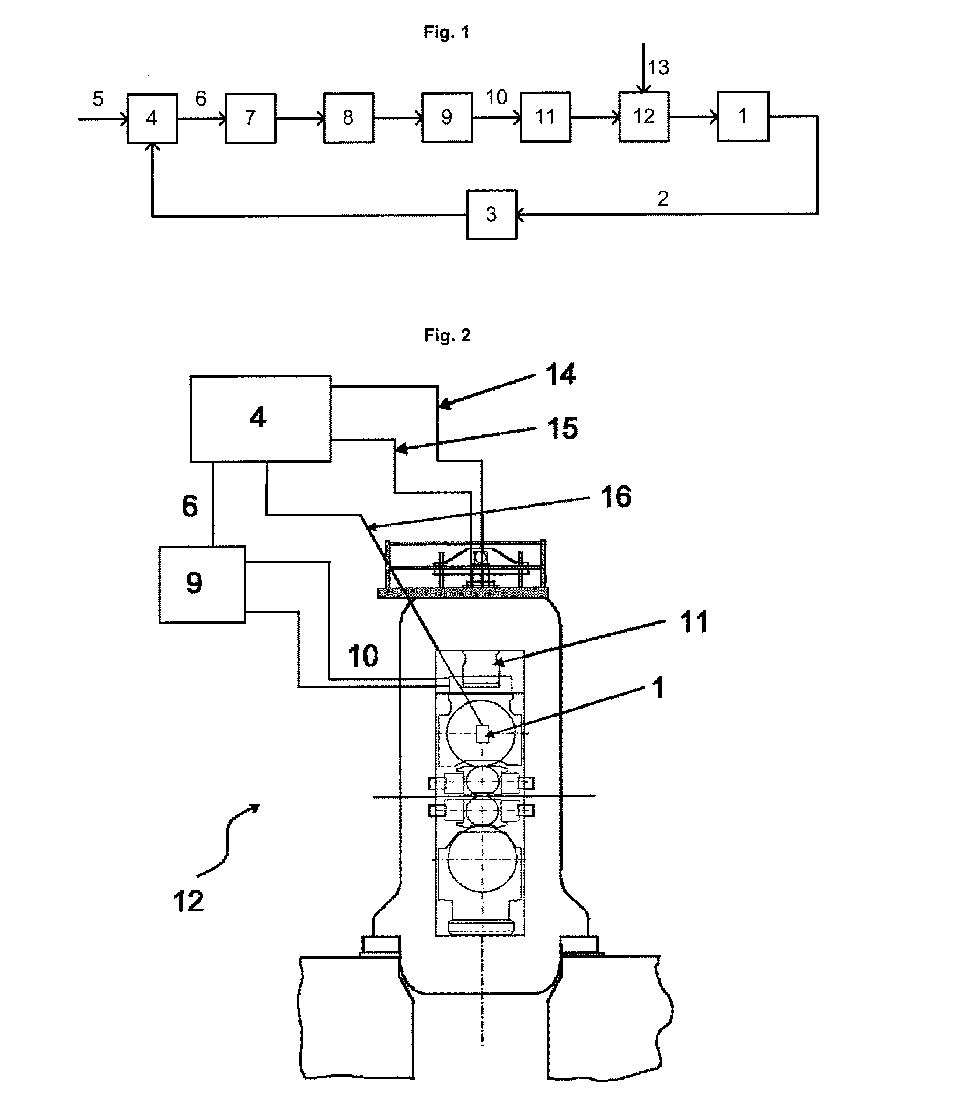
[0035]FIG. 1 shows the basic configuration of a controlled system for suppression of oscillations. A measurement variable 2 is supplied via an acceleration sensor 1, which is connected to a roller in a rolling stand 12, to a bandpass filter 3, which is in the form of a fourth-order bandpass filter and supplies that frequency component of the measurement variable, that is to say of the acceleration signal, which is relevant for chatter oscillations to a regulator 4. This regulator 4 contains a control algorithm and model elements which characterize the installation state and calculates at least one manipulated variable 6 in real time, taking account of the filter measurement variable 2 and a nominal variable 5, which manipulated variable 6 varies over time and is supplied to a lead / lag element 7, and then to a non-linear compensation element 8. A lead / lag element 7 makes it possible to vary the phase angle of a signal, in this specific case the manipulated variable 6. Such variation ...


PUM

PropertyMeasurementUnit
sampling timeaaaaaaaaaa
flow rateaaaaaaaaaa

Abstract

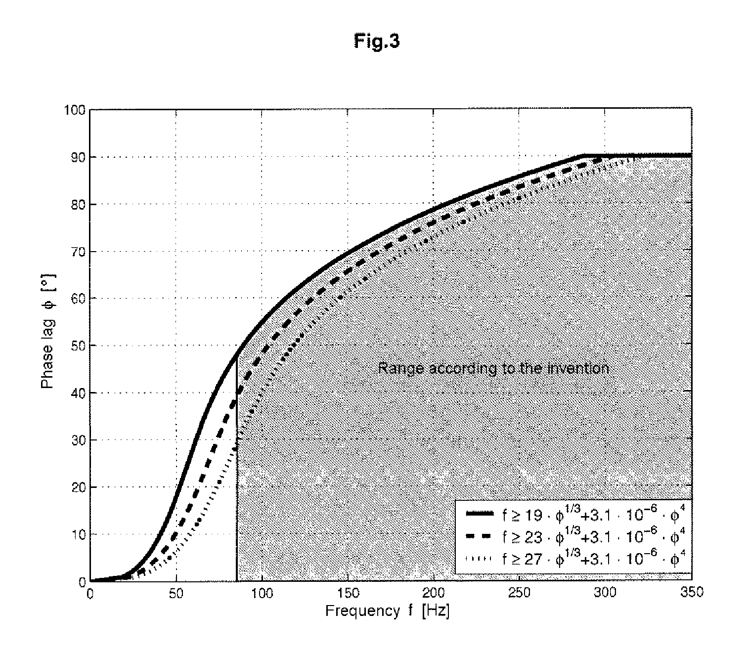
A method and an apparatus for suppression of oscillations in a rolling installation is described. By means of a hydraulic roller engagement third-octave oscillations are effectively suppressed, thus making it possible to improve the quality of the rolled material and / or the productivity of the rolling installation. A manipulated variable is supplied to an electrohydraulic actuating element that acts on at least one hydraulic actuator for the roller engagement and has a rated flow rate of ≧50 l / min. At least a portion of the frequency response at frequencies f≧80 Hz has a magnitude drop of ≦3 dB, and the phase lag φ in this frequency range satisfies the conditions f≧19·{square root over (φ)}+3.1·10−6·φ4 and φ<90°.

Description

CROSS-REFERENCE TO RELATED APPLICATIONS[0001]The present application is a 35 U.S.C. §371 national phase conversion of PCT / EP2009 / 055526, filed May 7, 2009, which claims priority of Austrian Application No. A979 / 2008 filed Jun. 18, 2008, the contents of which are incorporated by reference herein. The PCT International Application was published in the German language.FIELD OF THE INVENTION[0002]The present invention relates to a method and an apparatus for suppression of oscillations in a rolling installation.[0003]Specifically, the invention relates to a method for suppression of oscillations, in particular 3rd-octave oscillations, in a rolling installation having at least one rolling stand with roller engagement and having at least one roller set, wherein at least one permanently measured variable of the rolling installation is supplied to a regulator, a manipulated variable which varies over time is determined in real time with the aid of this regulator, and the controlled variable...

Claims


Application Information

Patent Timeline
Patent Type & Authority Patents(United States)
IPC IPC(8): B21B37/00B21B31/32
CPCB21B37/007
Inventor KEINTZEL, GEORGHOHENBICHLER, GERALD
Owner PRIMETALS TECH AUSTRIA GMBH
Learn More